Method for mechanical stoking in firing installations and firing installation

A combustion equipment and fuel technology, applied in the direction of combustion method, combustion equipment, fuel supply, etc., can solve the problems of not complying with the maximum allowable residual carbon content of ashes, and not being able to burn completely

Inactive Publication Date: 2011-01-12
SIEMENS AG OESTERR
View PDF1 Cites 1 Cited by
  • Summary
  • Abstract
  • Description
  • Claims
  • Application Information

AI Technical Summary

Problems solved by technology

[0004] The arrangement of the feeder above the end of the grate has the disadvantage that fresh fuel also emerges on the grate close to the end of the grate and can no longer be completely combusted before being discharged
As a result, the maximum permissible residual carbon content of ashes may not be respected

Method used


Image

  • Method for mechanical stoking in firing installations and firing installation
  • Method for mechanical stoking in firing installations and firing installation

Examples


Embodiment Construction

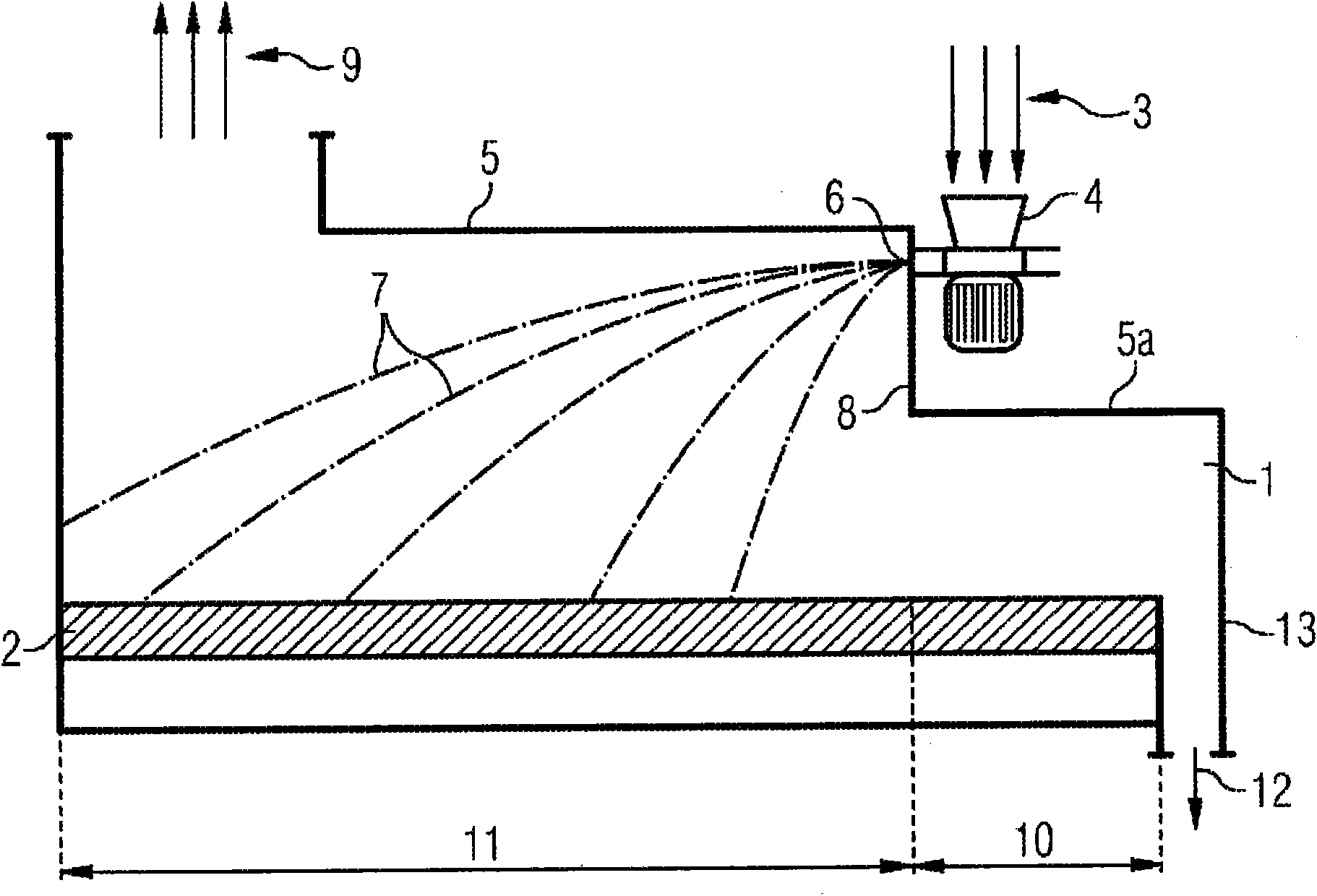
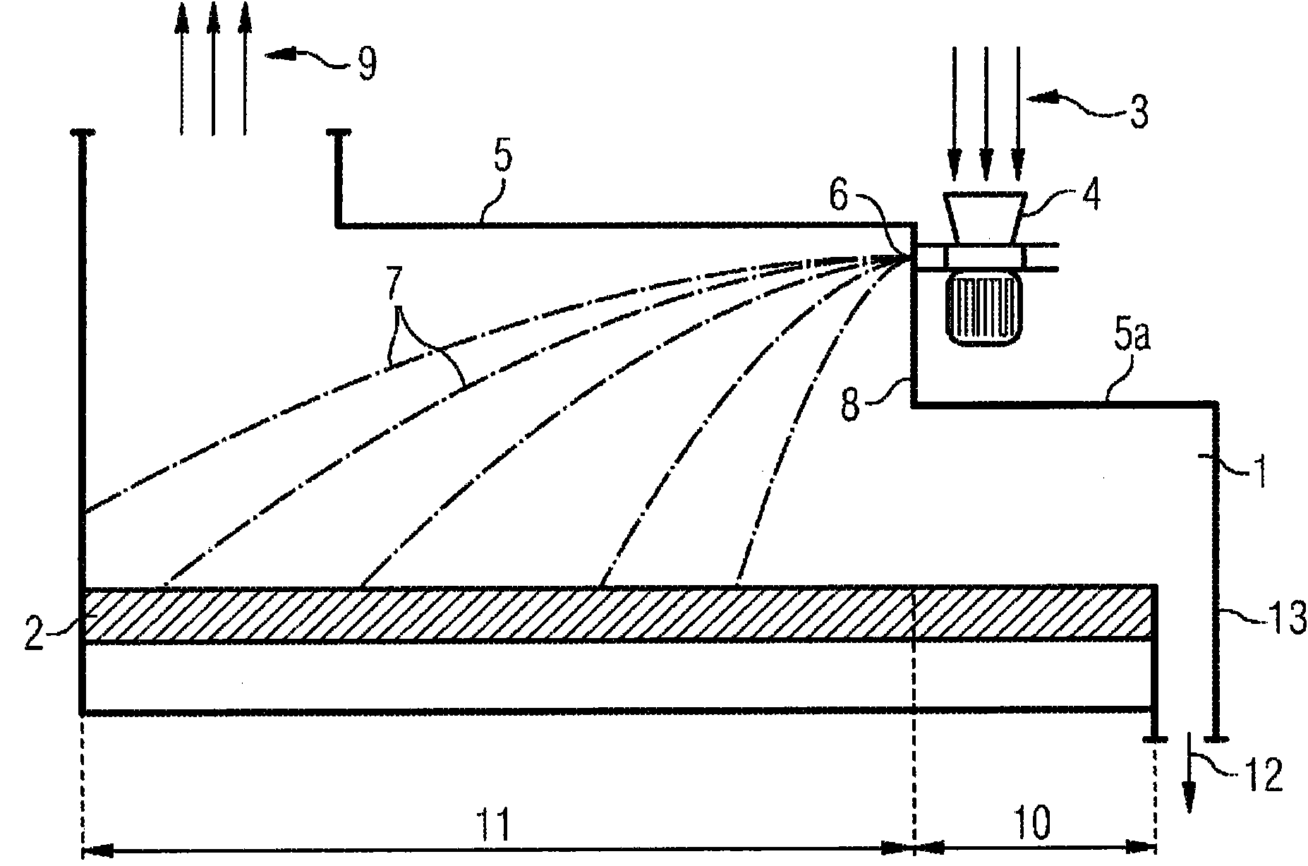
[0022] The drawing schematically shows a combustion chamber 1 of a combustion plant in which a grate 2 conveying from left to right is arranged horizontally. The feed grate consists of individual elements with rods oriented in the conveying direction (in this example the rods have a length of 500 mm), wherein only every second element moves back and forth. Fuel 3 is fed into feeder 4 from above and is conveyed into combustion chamber 1 by means of this feeder.

[0023] The feeder 4 has a centrifugal impeller arranged horizontally, ie the axis of rotation of the centrifugal impeller is vertical. The fuel 3 is placed in the feeder 4 from above in the region of the hub of the centrifugal impeller and is then conveyed horizontally outwards by means of the blades of the centrifugal impeller and through the openings of the feeder into the combustion chamber. As already mentioned above, the axis of rotation of the centrifugal impeller can also be inclined relative to the vertical. ...


PUM


Abstract

A method is disclosed for mechanical stoking in firing installations, in which fuel (3, 7) is applied using a mechanical stoker (4) to a grate (2), which is disposed in the firing chamber (1), wherein the mechanical stoker is oriented opposite the delivery direction of the grate (2), and a corresponding installation. The method is characterized in that the fuel (3, 7) is introduced directly belowthe firing chamber ceiling (5), viewed in the delivery direction of the grate (2) before the end of the grate, so that a burnout zone (10), which does not have fresh fuel (3, 7) applied thereto, is created on the grate (2) between the mechanical stoker (4) and the end of the grate (2). The residual carbon content of the ash can thus be decreased and a decrease of the rotational speed of the mechanical stoker can also be achieved.

Description

technical field [0001] The invention relates to a method for feeding fuel in a combustion plant and a corresponding combustion plant, wherein the fuel is placed on a grate arranged in the combustion chamber by means of a feeder, wherein the feeding direction is opposite to the conveying of the grate direction. Background technique [0002] The invention can be used in combustion equipment with a centrifugal impeller feeding device. In this case, solid, small-particle fuel is introduced into the combustion chamber by means of a centrifugal impeller arranged in the feeder. The range can be adjusted by changing the rotational speed of the centrifugal impeller. [0003] A corresponding installation is known, for example, from DE 42 17 070 A1, where the coal is placed on a horizontal grate by means of a charging device. Here, the feeder is arranged approximately vertically above the end of the grate in the end wall of the combustion chamber. [0004] The arrangement of the fe...

Claims


Application Information

Patent Timeline
Patent Type & Authority Applications(China)
IPC IPC(8): F23B40/02F23K3/18
CPCF23B40/02F23K3/18
Inventor D·鲍曼W·马德尔斯佩尔格W·魏斯
Owner SIEMENS AG OESTERR
Why Eureka
Try Eureka