Spiral puncture outfit and use method thereof

A puncture device and helical technology, applied in the field of helical puncture devices, can solve the problems of poor cutting ability of plastic cutters, stabbing internal organs of the human body, cutting tissue bleeding, etc., achieving firm fixation, controllable puncture force, and small tissue trauma Effect

Inactive Publication Date: 2011-01-19
莫易凡
View PDF9 Cites 4 Cited by
  • Summary
  • Abstract
  • Description
  • Claims
  • Application Information

AI Technical Summary

Problems solved by technology

The existing cutting knives are divided into two groups: sharp and blunt. The sharp ones are metal cutting knives, which have the advantage of high sharpness and can cut tissues more effectively, but at the same time, cutting tissues may cause bleeding, scratch internal organs, etc. Dangerous, the sharp knife adopts the method of vertical and continuous force entry into the abdomen, and once the end of the mandrel penetrates the muscle layer, the operator still uses force vertically, which will cause the cannula puncturer to enter the abdominal cavity too fast, which may stab the internal organs of the human body. Cause unnecessary damage; blunt cutter, and the front end of the mandrel is a plastic cutter, the cutting ability of the plastic cutter is poor, in order to allow the trocar trocar to enter the abdominal cavity, the cannula is now punctured by direct twisting and extrusion The device is sent into the abdominal cavity, that is, the operator holds the handle of the cannula trocar, rotates the cannula trocar left and right and squeezes the cannula trocar forward, so as to realize the entry of the cannula trocar. Some muscle fibers are broken, and once the end of the core rod penetrates the muscle layer, the operator still applies vertical force, which will cause the cannula trocar to enter the abdominal cavity too fast, which may stab the internal organs of the human body and cause unnecessary damage
Conical piercing core piercer operates like a blunt knife, and the above situations may also occur

Method used


Image

  • Spiral puncture outfit and use method thereof
  • Spiral puncture outfit and use method thereof
  • Spiral puncture outfit and use method thereof

Examples


Embodiment Construction

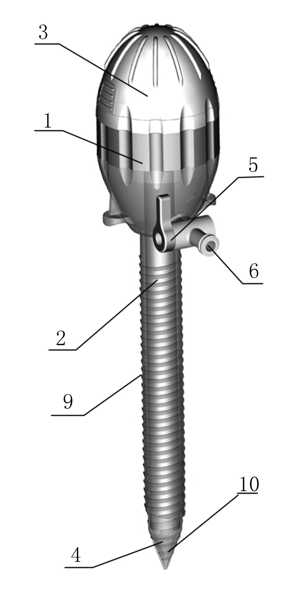
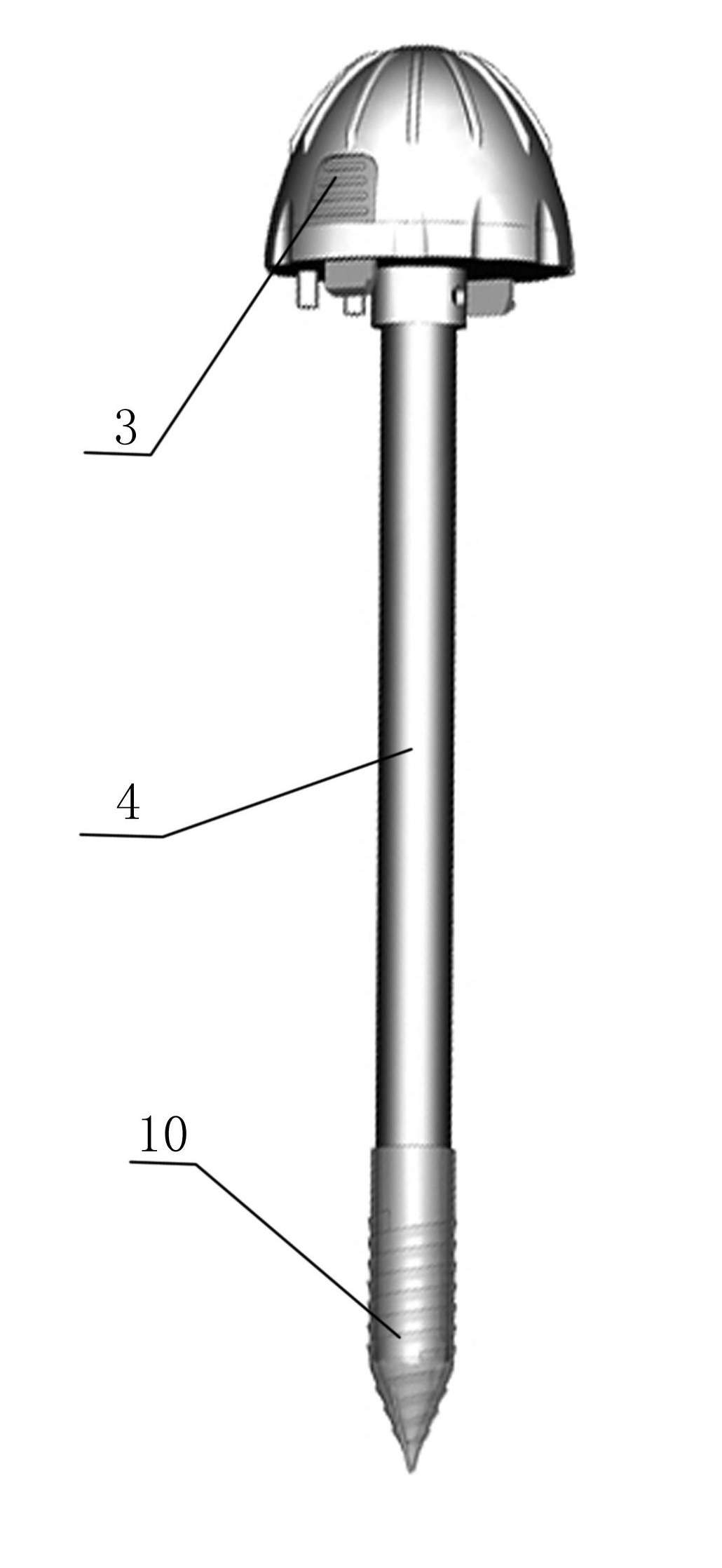
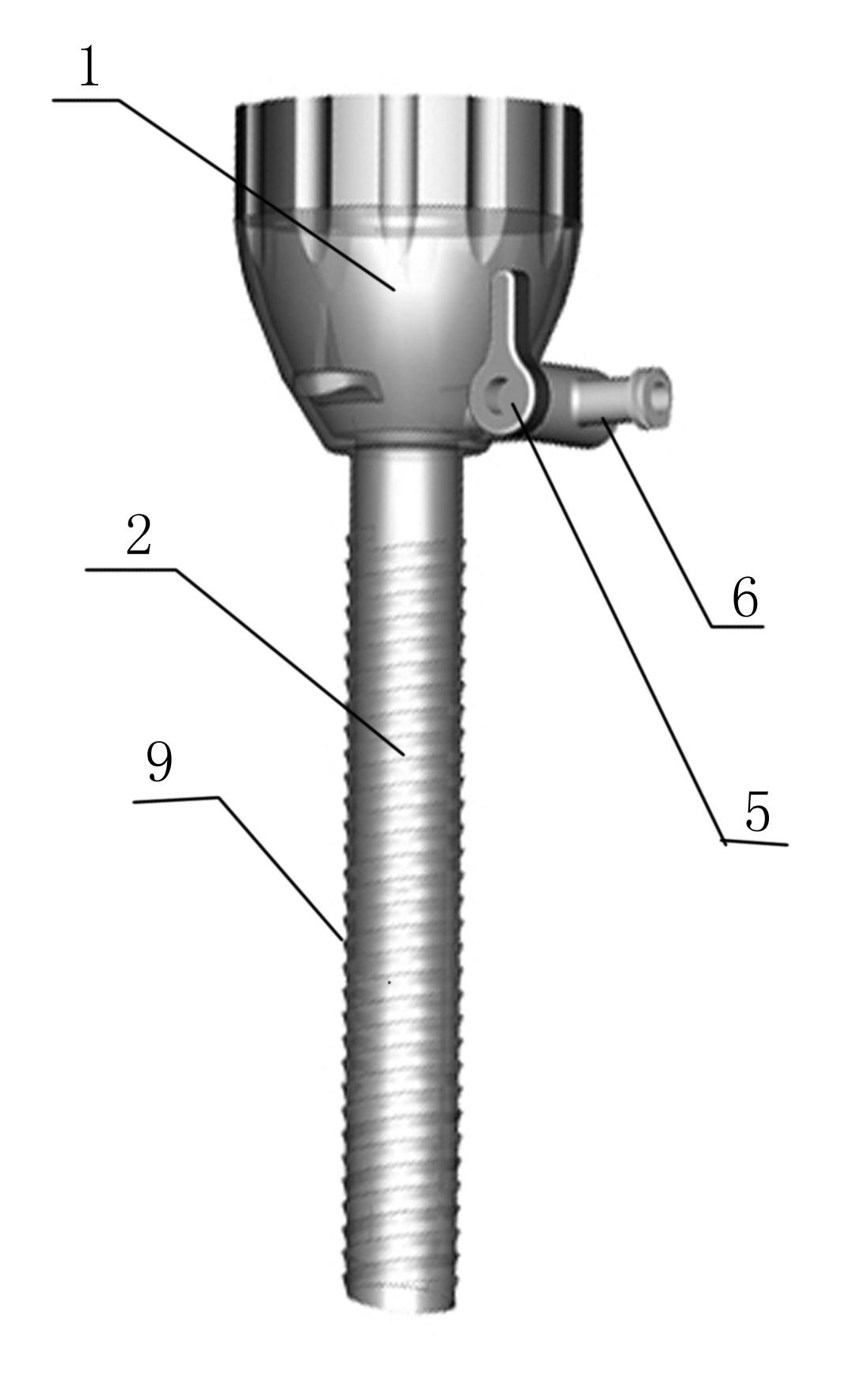
[0015] Such as Figure 1-4 As shown: the present invention is composed of a casing sheath 2 with a handle 1 at the tail and a core rod 4 with a core rod seat 3 at the tail. When in use, the core rod is inserted into the casing sheath and the core rod seat touches the handle. The front end of the mandrel will extend part of the area from the front end of the sheath, and then hold the handle and the mandrel seat to squeeze the invention into the abdominal cavity. The side of the sheath handle is provided with a vent tube 6 with an air valve 5 for accessing Gas, to maintain the existence of pneumoperitoneum, the inner cavity of the handle is provided with a rubber one-way valve 7 coaxial with the sleeve sheath, which is used to increase the friction between the core rod and the sleeve sheath with the handle and maintain air tightness; the handle The tail is provided with an opening 8 that is coaxial and communicated with the sleeve sheath. This opening is the entrance of the core...


PUM


Abstract

The invention provides a spiral puncture outfit which is simple to operate and reduces operative risks. The spiral puncture outfit comprises a sleeve sheath with a hand shank and a core bar with a core bar holder at the tail, wherein the side of the hand shank is provided with a breather pipe with an air valve; a rubber check valve coaxial with the sleeve sheath is arranged in the cavity of the hand shank; an opening coaxial and communicated with the sleeve sheath is arranged at the tail of the hand shank; the core bar is inserted into the sleeve sheath via the opening on the hand shank; and after the core bar stretches into the sleeve sheath till the end, the front end of the core bar stretches out of the sleeve sheath. The spiral puncture outfit is characterized in that continuous sheath threads are distributed on the outer wall of the sleeve sheath; and bar threads are arranged on the outer surface of the part of the front end of the core bar, which stretches out of the sleeve sheath after the core bar stretches into the sleeve sheath till the end. The spiral puncture outfit has the advantages of controllable puncture force, puncture speed and puncture depth, small tissue trauma, solid fixation, etc.

Description

technical field [0001] The invention relates to a spiral puncture device with simple operation and reduced operation risk and its application method. Background technique [0002] At present, the common cannula trocar is provided with lines (such as threads, sawtooth grooves, etc.) on the middle part of the outer wall of the cannula sheath. Tissues are in contact with each other to increase the frictional force and play the role of fixing the puncture device. [0003] The front end of the mandrel rod of the casing puncturer is provided with a cutting knife or a tapered puncture mandrel. The existing cutting knives are divided into two groups: sharp and blunt. The sharp ones are metal cutting knives, which have the advantage of high sharpness and can cut tissues more effectively, but at the same time, cutting tissues may cause bleeding, scratch internal organs, etc. Dangerous, the sharp knife adopts the method of vertical and continuous force entry into the abdomen, and onc...

Claims


Application Information

Patent Timeline
IPC IPC(8): A61B17/34
Inventor 莫易凡
Owner 莫易凡
Why Eureka
Try Eureka