Optical mouse

A technology of optical mouse and light-emitting surface, applied in the field of optical mouse, can solve the problem of high power loss in the light guide path, achieve the effects of reducing luminous power, increasing the included angle, and saving power consumption

Active Publication Date: 2012-04-18
BEIJING SUNPLUS TECH
View PDF0 Cites 0 Cited by
  • Summary
  • Abstract
  • Description
  • Claims
  • Application Information

AI Technical Summary

Problems solved by technology

[0013] The invention provides an optical mouse, which solves the problem of high power loss in the light guide path in the prior art

Method used


Image

  • Optical mouse
  • Optical mouse
  • Optical mouse

Examples


Embodiment Construction

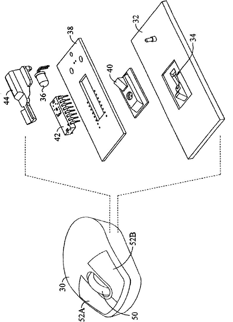
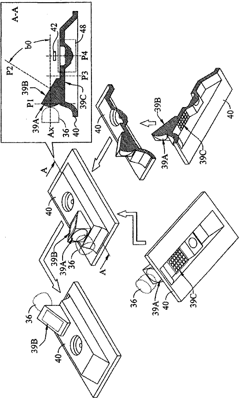
[0040] Please also refer to Figure 2 to Figure 4 , figure 2 What is shown is a schematic diagram of applying the light guide mechanism 40 to an optical mouse 30 according to an embodiment of the present invention, image 3 The light guide mechanism 40 of the present invention is shown in views and cross-sectional structures from different angles, Figure 4 Then, the light guiding path of the light guiding mechanism 40 is shown. Such as figure 2 As shown, the optical mouse 30 of the present invention is provided with a light source 36 , a light guiding mechanism 40 and a sensor 42 arranged in an integrated circuit. The optical mouse 30 can be provided with a scroll wheel 50, a plurality of buttons 50A and 50B, and / or a wireless module and a power supply module etc. (not shown in figure 2 ).

[0041]In the optical mouse 30, the light source 36 is used for converting electrical energy into light energy to emit light; Light-emitting diodes made of or similar materials ca...


PUM


Abstract

The invention discloses an optical mouse, which is provided with a light guide mechanism. The light guide mechanism comprises a light collecting surface, a single reflection surface and a light emergent surface. The light from a guide light source is subjected to three times of interface actions of refraction, reflection and refraction, and then is incident to a tracking surface so as to reduce the loss of the optical power caused by too much interface contacts and increase the included angle formed by the incident light on the tracking surface. The light emergent surface can be provided witha micro lens matrix as a light diffuser to improve the optical property and the distribution of the light incident to the tracking surface.

Description

technical field [0001] The present invention relates to an optical mouse, in particular to an optical mouse with a light guiding mechanism to reduce the interface contact times in the light guiding path, increase the incident angle of the tracking surface, and improve the optical properties of the microlens matrix. Background technique [0002] The optical mouse is one of the most widely used computer peripherals in the modern information society. How to improve the performance and reduce the cost of the optical mouse has also become the research and development focus of modern information manufacturers. [0003] Please refer to figure 1 , which shows a cross section of a conventional optical mouse 10 . When the optical mouse 10 realizes its pointing function, the optical mouse 10 will incident the light on a plane 26 (also called the tracking surface), and sense the light reflected by the plane 26, so as to judge according to the difference of the reflected light. Displac...

Claims


Application Information

Patent Timeline
Patent Type & Authority Patents(China)
IPC IPC(8): G06F3/033G06F3/0354
Inventor 朱济群
Owner BEIJING SUNPLUS TECH
Why Eureka
Try Eureka