
Rail joint transverse dislocation detection device and method

A technology of lateral dislocation and detection devices, which is applied in transportation and packaging, railway vehicle shape measuring devices, railway car body parts, etc., can solve the problem of affecting the efficiency and benefits of railway transportation, and cannot realize real-time, dynamic remote, large-scale Problems such as batch misalignment detection and low measurement accuracy can achieve the effect of prolonging railway operation time, reliable detection results and high precision

Active Publication Date: 2016-10-12
SICHUAN JINMA TECH
View PDF7 Cites 1 Cited by
  • Summary
  • Abstract
  • Description
  • Claims
  • Application Information

AI Technical Summary

Problems solved by technology

This traditional detection method has the following problems: 1) The detection can only be completed after the train is stopped. Generally, the train needs to be stopped at 1-4 in the morning to cooperate with the safety inspection, which greatly affects the efficiency and benefit of railway transportation. very limited use
2) Rely on the experience of engineering personnel to judge whether the track inspection vehicle has a sense of lateral vibration when passing the joint, and the measurement accuracy is not high
3) Real-time, dynamic, remote, large-scale batch dislocation detection cannot be realized

Method used


Image

  • Rail joint transverse dislocation detection device and method
  • Rail joint transverse dislocation detection device and method
  • Rail joint transverse dislocation detection device and method

Examples


Embodiment Construction

[0034] The technical solution of the present invention will be further described in detail below in conjunction with the accompanying drawings, but the protection scope of the present invention is not limited to the following description.

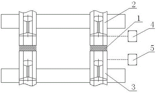
[0035] like figure 1 As shown, the lateral dislocation detection device for track joints is used to detect the lateral dislocation between adjacent rails (the first rail 2 and the second rail 3) at the track joint 1, and a set of Ranging sensors, each group of ranging sensors includes at least two ranging sensors, the first ranging sensor 4 is arranged on the side of the first rail 2, the first ranging sensor 4 is used to detect the first rail 2 and the first ranging sensor The lateral distance between the sensors 4; the second ranging sensor 5 is arranged on the side of the second rail 3, and the second ranging sensor 5 is used to detect the lateral distance between the second rail 3 and the second ranging sensor 5; for To ensure the reli...


PUM


Abstract

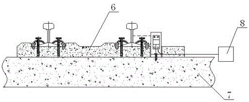
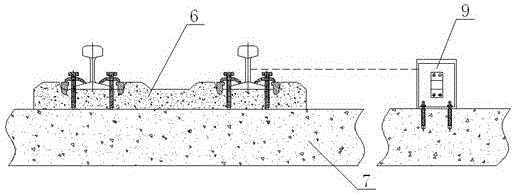
The invention discloses a rail joint transverse dislocation detection device and method. The detection device comprises at least two distance-measuring sensors; the distance-measuring sensors are arranged on side faces of a steel rail; the distance-measuring sensors are used for detecting a transverse distance between the steel rail and the distance-measuring sensors; the distance-measuring sensors are fixedly mounted on a sleeper (6) or a base (7) of the rail. The detection method comprises: mounting the rail joint transverse dislocation detection device; carrying out reference measurement and calculating a reference transverse distance difference; carrying out dislocation detection and calculating an instant transverse distance difference; comparing numerical values of the reference transverse distance difference and the instant transverse distance difference and analyzing dislocation. After the device disclosed by the invention is mounted, real-time detection can be realized; the detection process does not influence the normal running of a train and the utilization is convenient and safe. By detecting the distance between the sensors with the fixed positions and the steel rail, transverse dislocation of the steel rail is judged and a detection result is reliable and has high precision. Dynamic and remote rail joint dislocation detection can be realized so that the rail joint transverse dislocation detection device and method can be applied to large-scale and large-batch detection.

Description

technical field [0001] The invention relates to a railway safety detection device, in particular to a detection device and method for lateral dislocation of rail joints. Background technique [0002] After more than ten years of development, China's railways have gradually entered the ranks of developed countries with high-speed railways in the world. The process of maintenance mechanization has laid a good foundation for the safety of my country's high-speed railway transportation technology. The process of speed-up transformation has also promoted the development of track detection technology. [0003] With the deepening of the speed-up reconstruction project, the use of ballastless track is becoming more and more extensive. Ballastless track, also known as ballastless track, refers to a track structure that uses an integral foundation such as concrete and asphalt mixture to replace the loose-grained gravel track bed. The sleeper itself is made of poured concrete, and th...

Claims


Application Information

Patent Timeline
Patent Type & Authority Applications(China)
IPC IPC(8): B61K9/08H04L29/08
CPCB61K9/08H04L65/40
Inventor 杨绍荃杨波
Owner SICHUAN JINMA TECH
Learn More