Light modulating control circuit, chip and method

A dimming control circuit and dimming control technology, applied in the direction of adjusting electrical variables, lamp circuit layout, control/regulation system, etc., can solve problems such as input current oscillation, dimmer not working normally, low average voltage, etc., to achieve The effect of effective regulation

Active Publication Date: 2011-01-19
BYD SEMICON CO LTD +1
View PDF6 Cites 44 Cited by
  • Summary
  • Abstract
  • Description
  • Claims
  • Application Information

AI Technical Summary

Problems solved by technology

[0005] Most fluorescent and LED lights will state that they are not suitable for use with triacs or other dimmers, because they are not a true resistive load for a Triac dimmer, for the following reasons: General AC / DC switch mode LEDs The driver cannot adapt to the sudden rise in voltage and lower average voltage in the second half cycle; when the Triac dimmer is turned on, it will charge the LC filter at the input, which may cause oscillation of the input current; many AC / DC The LED driver uses a simple bridge rectification method
According to this method, the dimmer will only draw the power supply current for a very short time, so the dimmer does not have the current to maintain continuous conduction, and the dimmer cannot work normally

Method used


Image

  • Light modulating control circuit, chip and method
  • Light modulating control circuit, chip and method
  • Light modulating control circuit, chip and method

Examples


Embodiment Construction

[0037] Embodiments of the invention are described in detail below, examples of which are illustrated in the accompanying drawings. The embodiments described below by referring to the figures are exemplary only for explaining the present invention and should not be construed as limiting the present invention.

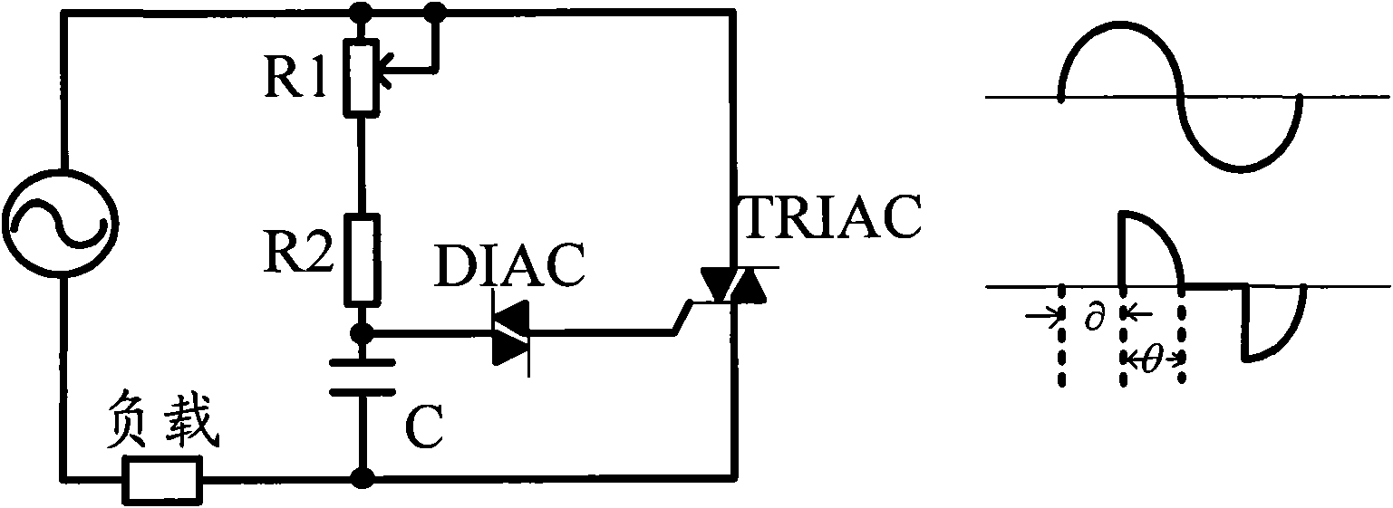
[0038] Commonly used existing dimmers include thyristor dimmers, and of course other dimmers that use MOS (Metal Oxide Semiconductor) to realize dimming. The embodiments of the present invention are applicable to various dimmers commonly used at present. The following description takes a silicon controlled rectifier as an example to illustrate the principle and implementation method of dimming. Of course, this is only an example and does not limit the scope of the present invention.

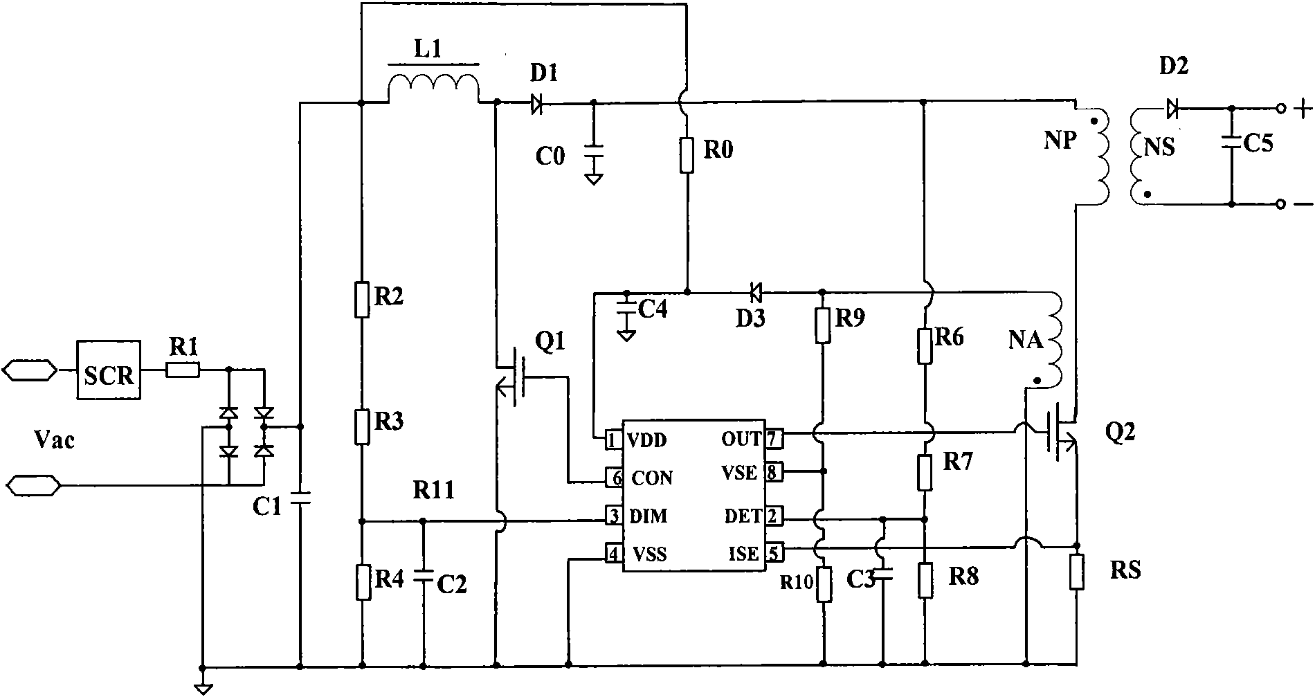
[0039] Such as figure 2 Shown is a schematic structural diagram of a dimming control circuit according to an embodiment of the present invention. The dimming control circuit includes a ...


PUM


Abstract

The invention provides light modulating control circuit, chip and method. The light modulating control circuit is suitable for being connected with a light modulator for controlling a light-emitting device. The light modulating control circuit comprises a boosting control module, a constant current control module and a light modulating control module, wherein the boosting control module is used for boosting the input voltage of the light modulating control circuit and maintaining a voltage difference of the output voltage and the input voltage of the light modulating control circuit in a certain range so as to maintain the synchronization of the voltage at both ends of the light modulator and current passing through the light modulator; the constant current control module is used for maintaining the stability of the output current of the light modulating control circuit when the light modulating signal is not changed; and the light modulating control module is used for changing the output current of the light modulating control circuit according to the change of the light modulating signal of the light modulator. The light modulating control circuit, chip and method provided by the invention can ensure that the light modulator normally works and realizes effective adjustment on an illuminating device.

Description

technical field [0001] The present invention generally relates to the technical field of electronic circuits, and more specifically relates to dimming control of lighting devices. Background technique [0002] With the increasing awareness of environmental protection and energy saving, LEDs are constantly being used in various lighting occasions. As the cost of high-brightness LEDs continues to decrease and their performance continues to improve, it is expected that in the near future, the luminous efficacy of LEDs will be comparable to compact fluorescent lamps, and LEDs have the advantages of longer life and no mercury. If you want to dim the lighting lamps, the most common brightness control method is to use Triac (triac triac) dimmers for dimming, but its disadvantage is that it is only suitable for incandescent bulbs or halogen lamps. In order to use Triac dimmers to dim LEDs, it is necessary to ensure that the SCR can work normally. [0003] Such as figure 1 The wor...

Claims


Application Information

Patent Timeline
Patent Type & Authority Applications(China)
IPC IPC(8): H05B37/02H02M3/145H02M1/08
Inventor 李林锋杨小华
Owner BYD SEMICON CO LTD
Why Eureka
Try Eureka