

Turbo molecular pump
A turbomolecular pump and stator technology, which can be used in pumps, pump components, axial flow pumps, etc., to solve problems such as reduced efficiency of turbomolecular pumps
- Summary
- Abstract
- Description
- Claims
- Application Information
AI Technical Summary
Problems solved by technology
Method used
Image

Examples
Embodiment Construction
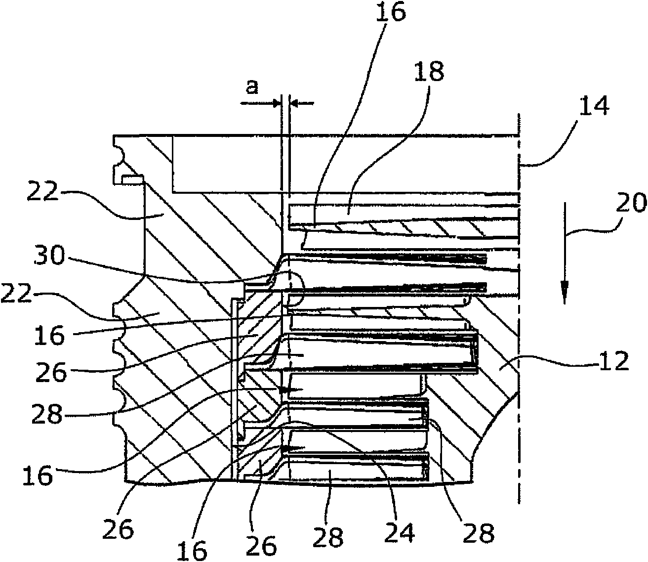
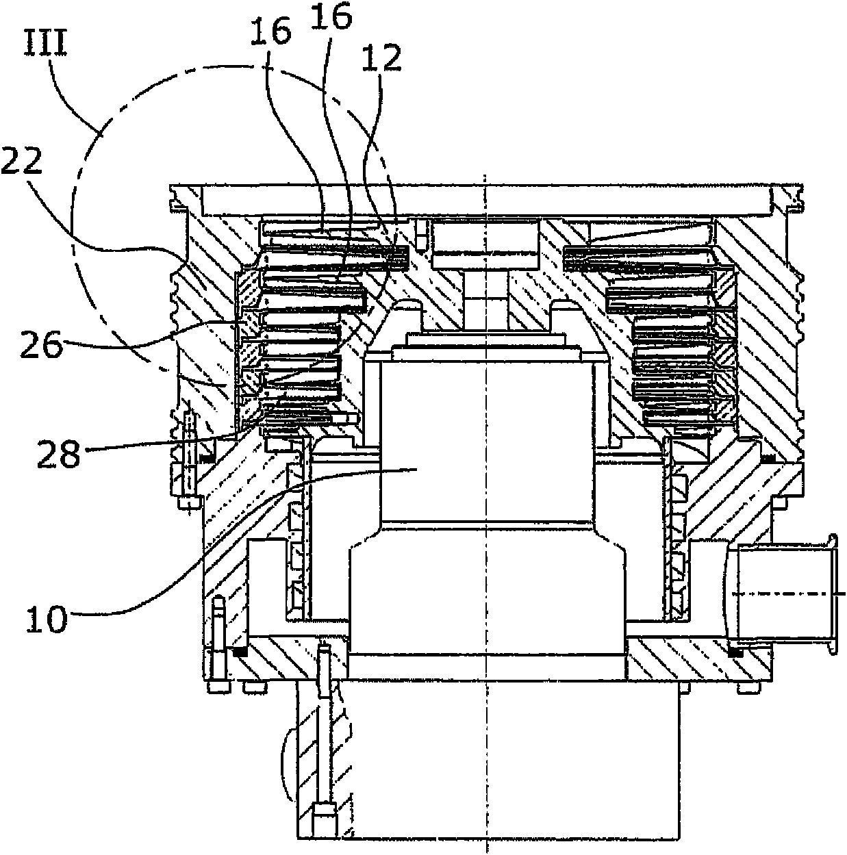
[0016] follow in figure 1 An embodiment of a turbomolecular pump according to the prior art is shown in , showing a drive shaft 10 ( figure 2 ) on the rotor 12. The rotor 12 has rotor vanes 16 extending radially with respect to the longitudinal axis 14 or the axis of rotation of the shaft 10 . Each rotor vane has a rotor blade 18 which is suitable so that in the gas to be conveyed parallel to the longitudinal axis, that is to say at figure 1 Downward in the direction of arrow 20 produces the main flow direction. The rotor 12 is arranged in a housing 22 , wherein the housing for accommodating the rotor has a cylindrical, optionally stepped, recess 24 .
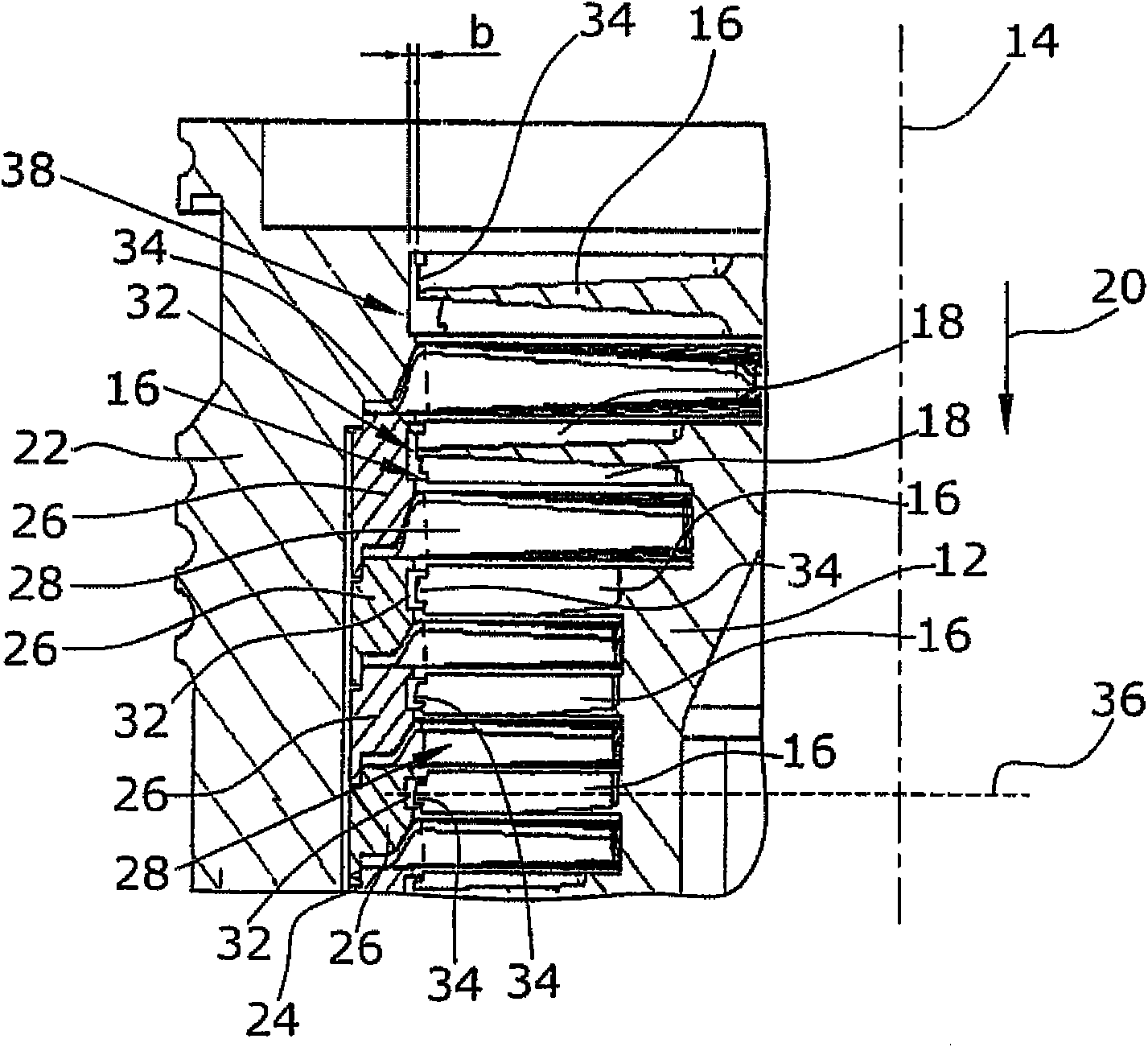
[0017] Part of the rotor blade 16 is surrounded by a stator ring 26 . The stator ring 26 is arranged continuously in the longitudinal direction 14 and thus covers the inner side of the cylindrical groove 24 of the housing 22 . Arranged between adjacent stator rings 26 are stator disks 28 facing inwards in the direction of...
PUM
 Abstract
Description
Claims
Application Information