
Handrail assembly and stand combination

A handrail and frame technology, which is applied in the field of installation structure of handrail components of generator sets, can solve problems such as inconvenient operation, poor safety, scrapped cartons, etc., achieve good reliability and safety, improve convenience, and facilitate operation

Inactive Publication Date: 2011-01-26
力帆科技(集团)股份有限公司
View PDF3 Cites 1 Cited by
  • Summary
  • Abstract
  • Description
  • Claims
  • Application Information

AI Technical Summary

Problems solved by technology

Since the handle can swing up and down within a certain range around the connection point between the hook and the armrest seat, when the operator releases the hand, the handle will hang down freely, and when using it again, the handle must be lifted upwards, which is inconvenient to operate on the one hand; On the other hand, when moving the generator set, you can only hold the handle and push it forward, and you cannot pull the handle to drag the generator set, otherwise it will easily cause the handle to be separated from the frame, which will affect the convenience of moving the generator set
When pushing the generator set downhill, the operator's force is on the movable handle. Once an emergency occurs, it is difficult to stop the machine in time, and the safety is poor.
In addition, the armrest seat is welded on the frame, and a larger carton is required for packaging and transportation, which will increase the cost of packaging and transportation; the corners of the armrest seat are also easy to puncture the carton, causing the carton to be scrapped

Method used


Image

  • Handrail assembly and stand combination
  • Handrail assembly and stand combination
  • Handrail assembly and stand combination

Examples


Embodiment Construction

[0021] Below in conjunction with accompanying drawing and embodiment the present invention will be further described:

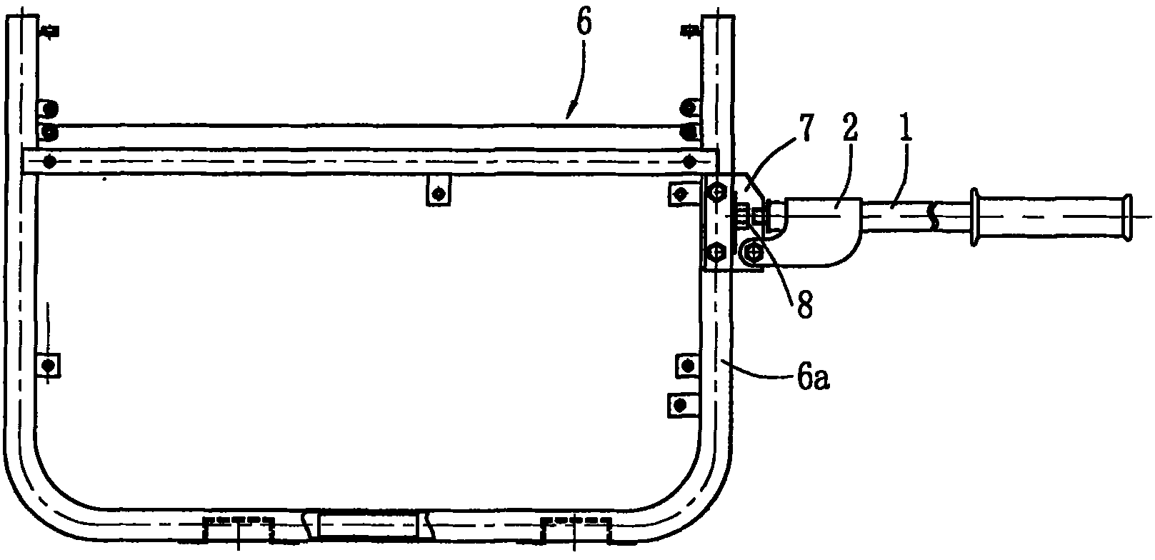
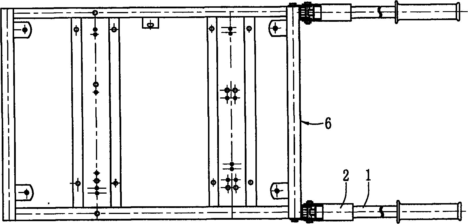
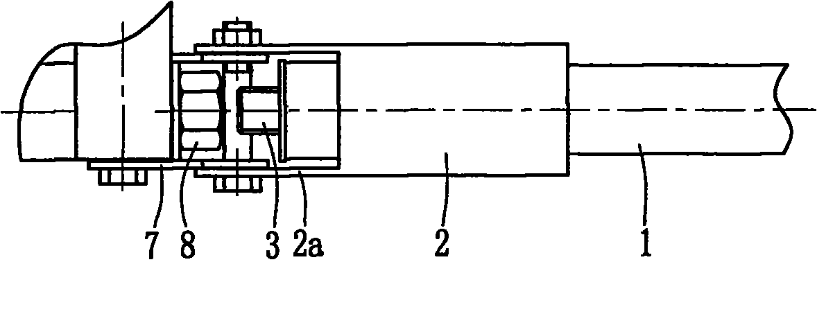
[0022] From Figure 1 to Figure 8 As can be seen, the present invention is made of handle 1, support 2, stud 3, bushing 4, rubber sleeve 5, frame 6, armrest seat 7 and nut 8. The handle 1 is a straight-through pipe structure, in the handle 1 such as Figure 4 The shown right end is sheathed with a rubber sleeve 5, and the left end of the handle 1 is provided with a stud 3. The stud 3 is a stepped cylindrical structure, and the axis of the stud 3 is on the same line as the axis of the handle 1 . The small cylindrical section of the stud 3 is processed with external threads, and the large cylindrical section of the stud 3 extends into the handle 1 and is fixed by welding with the handle 1. A ring of bosses 3 a are integrally formed at the end of the large cylindrical section of the stud 3 , and the bosses 3 a abut against the end surface of the handle 1 .

...


PUM


Abstract

The invention discloses a handrail assembly and stand combination which comprises a stand, handrail seats, handles, a support and a stud. Two handrail seats are arranged on one end of the stand side by side, and each handrail seat is provided with one handle. One end of each handle passes through the n-shaped support and is fixedly connected with the stud, and the stud is connected with a corresponding nut on the stand in a threaded mode. Support lugs are symmetrically arranged on the lower end of the support, the two support lugs are located on both sides of the lower part of the stud, and the support lugs are connected with the corresponding handrail seats on the stand through bolts. The handrail assembly and stand combination can be integrated with a stand through rigid connection, which not only is convenient for operation, but also can increase the convenience for moving a generator set. Moreover, the handrail assembly and stand combination can stop the machine at any time when the generator set moves on a down slope. The invention has the characteristics of simple structure, firm connection, easy disassembly and assembly, good reliability and safety and the like, and can be applied to various types of generator units.

Description

technical field [0001] The invention belongs to the technical field of generator sets, and in particular relates to the installation structure of the armrest assembly of the generator set. Background technique [0002] At present, the armrest assembly on the generator set frame generally consists of a handle and a hook, the hook is fixed on one end of the handle, and the handle is movably connected with the armrest seat on the frame through the hook. Since the handle can swing up and down within a certain range around the connection point between the hook and the armrest seat, when the operator releases the hand, the handle will hang down freely, and when using it again, the handle must be lifted upwards, which is inconvenient to operate on the one hand; On the other hand, when moving the generator set, you can only hold the handle and push it forward, and you cannot pull the handle to drag the generator set, otherwise it is easy to cause the handle to be separated from the ...

Claims


Application Information

Patent Timeline
IPC IPC(8): H02K15/14
Inventor 吕和
Owner 力帆科技(集团)股份有限公司
Learn More