On-line optical cable monitoring method

A technology of optical cables and lasers, which is applied in the field of optical fiber communication, can solve the problems of difficult filtering and separation of optical pulse signals, affecting communication services, and large ripples in OTDR curves, and achieves stable optical wavelength and optical power, low optical intensity noise, and small curve ripples. Effect

Active Publication Date: 2011-01-26
GUILIN G LINK TECH
View PDF8 Cites 10 Cited by
  • Summary
  • Abstract
  • Description
  • Claims
  • Application Information

AI Technical Summary

Problems solved by technology

[0009] 1. When the optical cable communication system is a 1310nm / 1550nm wavelength division multiplexing system, because the spectral width of the FP-LD laser is relatively wide, no matter whether the wavelength of the OTDR test light is 1310nm or 1550nm, the OTDR test optical pulse signal will be generated with the communication service optical signal Mutual interference, affecting communication services and inaccurate measurement
[0010] 2. If the distance of the fiber optic cable to be monitored is too long, and two OTDRs are required to monitor simultaneously from both ends of the fiber optic cable, due to the wide spectral width of the FP-LD laser, it is difficult to filter and separate the two OTDR test optical pulse signals , which directly affects the test results
Although the spectral width of the DFB-LD laser is narrow, it is easy to filter and separate, and has little impact on the optical signal of the communication service. However, due to the influence of the light intensity noise of the DFB-LD laser itself, the OTDR curve obtained by using it to measure the light has large ripples. , which directly affects the analysis and judgment of the optical cable on-line monitoring equipment on the optical cable status and event points
[0012] To sum up, the existing OTDR in optical cable online monitoring equipment is difficult to meet the needs of optical cable online monitoring: one is to ensure the quality of the curve, and the other is not to affect the communication business

Method used


Image

  • On-line optical cable monitoring method
  • On-line optical cable monitoring method
  • On-line optical cable monitoring method

Examples


Embodiment 1

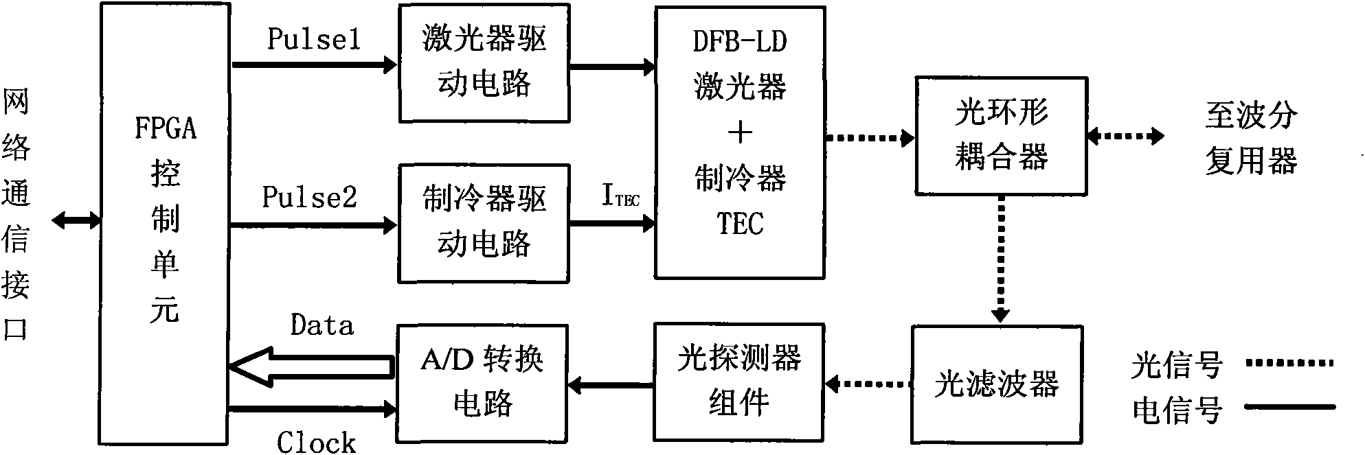
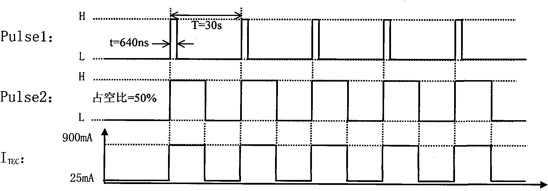
[0041] see figure 1 .

[0042] In the optical time domain reflectometer, the laser connected to the optical ring coupler is a DFB-LD laser with a cooler, and the cooler and the DFB-LD laser are respectively connected to the cooler drive circuit and the laser drive circuit. The cooler drive circuit, Both the laser drive circuit and the A / D conversion circuit are connected to the FPGA control unit, the FPGA control unit is connected to the network communication interface, the optical ring coupler is also connected to the wavelength division multiplexer and the optical filter, and the optical filter passes through the optical detector assembly Connect with A / D conversion circuit.

[0043]FPGA control unit, used to generate control signals, receive A / D conversion data and average processing, network communication, etc.;

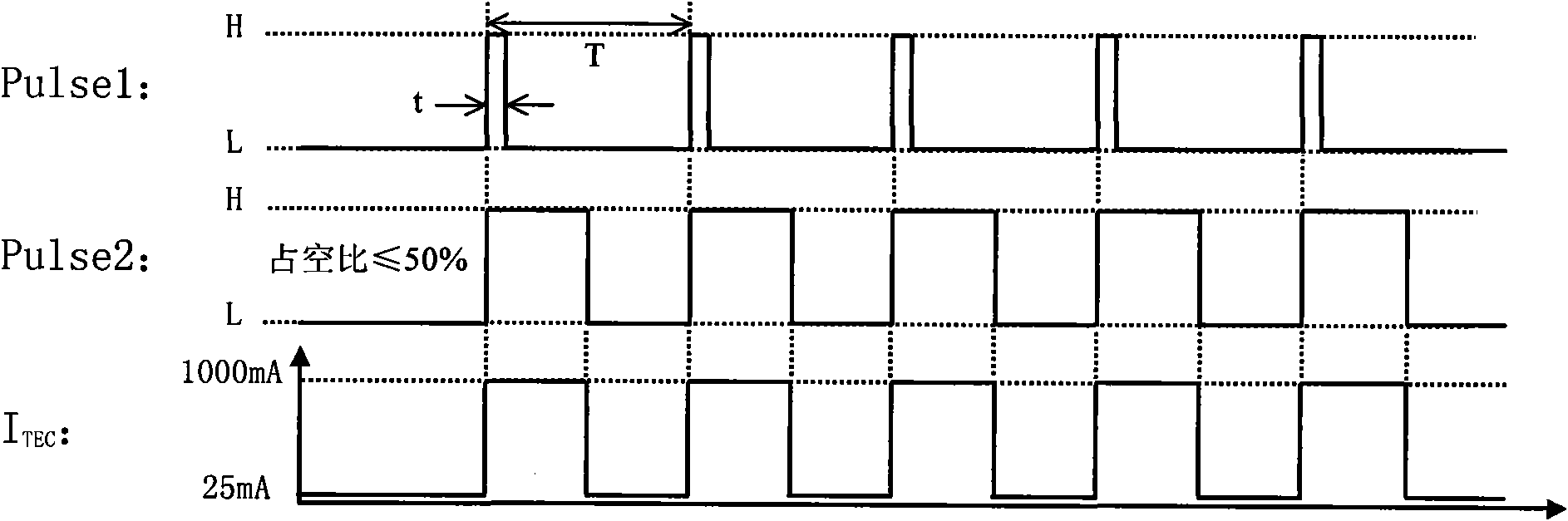
[0044] Pulse1, the periodic pulse signal generated by the FPGA control unit, is used to control the laser drive circuit, and then the DFB-LD laser sends out a ...

Embodiment 2

[0066] Referring to Example 1. The changed parameters are as follows: I TEC = 500mA.

[0067] Pulse1, Pulse2 and I TEC For a schematic diagram of the relationship see Figure 5 ; Obtain OTDR curve, see Image 6 ;

Embodiment 3

[0069] Referring to Example 1. The changed parameters are as follows: The duty cycle of Pulse2 is 10%.

[0070] Pulse1, Pulse2 and I TEC For a schematic diagram of the relationship see Figure 7 ; Obtain OTDR curve, see Figure 8 ;


PUM


Abstract

The invention discloses an improved on-line optical cable monitoring method. In an optical time domain reflectometer, a laser connected with a ring coupler is a DFB-LD laser with a refrigerator; the refrigerator and the DFB-LD laser are respectively connected with a refrigerator driving circuit and a laser driving circuit; the refrigerator driving circuit, the laser driving circuit and an A / D conversion circuit are connected with an FPGA control unit; and the FPGA control unit is connected with a network communication interface. During monitoring, the refrigeration current of the refrigerator is 500-900mA, pulse signals Pulse1 for starting the laser driving circuit and square signals Pulse2 for starting the refrigerator driving circuit, which are generated by the FPGA control unit, have the same period of 10-30s, and the duty ratio of the square signals Pulse2 is less than or equal to 50 percent. The method has the advantages of reducing light intensity noise, having small OTDR curve waves, little influencing optical signals in communication service, meeting the requirement of on-line optical cable monitoring, and improving the accuracy of analyzing and judging optical cable states and event points by on-line optical cable monitoring equipment.

Description

technical field [0001] The invention relates to optical fiber communication, in particular to a method for online monitoring of optical cables. Background technique [0002] With the rapid development of optical fiber communication technology and the continuous expansion of optical networks, the daily maintenance and safety of optical cables are becoming more and more important. For some special optical cable lines carrying important information, in order to ensure their unimpeded, safe and reliable, the optical cable online monitoring is carried out. Optical time domain reflectometer (ie OTDR) plays a very important role in the optical cable online monitoring equipment. [0003] OTDR is actually a testing instrument based on the principles of Rayleigh scattering and Fresnel reflection. By controlling the OTDR light source, a series of test light pulses are periodically sent out and injected into the optical fiber. Due to the occurrence of Rayleigh backscattering and Fresn...

Claims


Application Information

Patent Timeline
Patent Type & Authority Applications(China)
IPC IPC(8): H04B10/08G02B6/44H04B10/071
Inventor 肖丹谊黄凤玲周晓伟拱息发李立汉刘福奇
Owner GUILIN G LINK TECH
Why Eureka
Try Eureka