
Video passenger flow monitoring system and method

A monitoring system and passenger flow technology, which is applied in the field of passenger flow monitoring system and intelligent video passenger flow monitoring system, can solve the problems of being unable to maneuver flexibly, keeping in touch with the control room to grasp at any time, and consuming a lot of manpower, etc., to achieve the effect of flexible and efficient configuration

Active Publication Date: 2012-06-06
JIANGSU KEDA HUIFENG SCI & TECH
View PDF5 Cites 0 Cited by
  • Summary
  • Abstract
  • Description
  • Claims
  • Application Information

AI Technical Summary

Problems solved by technology

But at the same time, there are still many defects in the video surveillance technology mainly based on manual surveillance: traditional video surveillance relies on manual labor, consumes a lot of manpower, but is limited by various defects of manpower, time-consuming, labor-intensive and low in efficiency
The monitoring personnel are on duty in the monitoring room. In case of any abnormal situation, they will call the police or send personnel to check and deal with it on the spot. When the monitoring room duty officer leaves the monitoring room, he will not be able to grasp the situation. It is necessary to keep in touch with the monitoring room to keep abreast of the overall or regional situation
This type of structure requires a large number of on-duty and patrolling personnel, and cannot handle dangerous situations flexibly and in a timely and effective manner.

Method used


Image

  • Video passenger flow monitoring system and method
  • Video passenger flow monitoring system and method
  • Video passenger flow monitoring system and method

Examples


Embodiment Construction

[0036] The present invention will be further described below in conjunction with the accompanying drawings and specific embodiments.

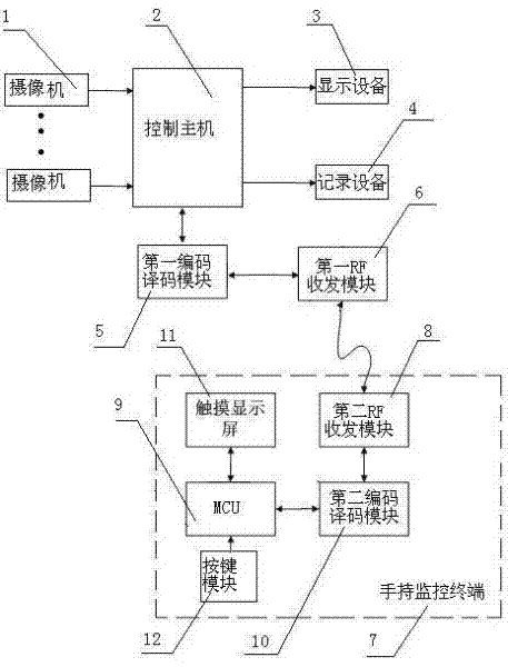
[0037] like figure 1 As shown, the video passenger flow monitoring system includes a plurality of cameras 1, a control host 2, a display device 3, and a recording device 4. The cameras 1, display devices 3, and recording devices 4 are connected to the control host 2. Device 4 is located in the monitoring room. The camera 1 is a network camera, the number of which can be determined according to the scope of the monitoring site, and can be installed in shopping malls, entrances and exits of exhibition halls, traffic arteries, areas with safety risks, etc. as required. Camera 1 is installed five meters above the ground, the lens is perpendicular to the ground, and the top view is on the monitored area. The output image format of camera 1 is RGB888 or YCbCr422, the frame rate of the image is greater than 15fps, and the image resolution is 640×480....


PUM


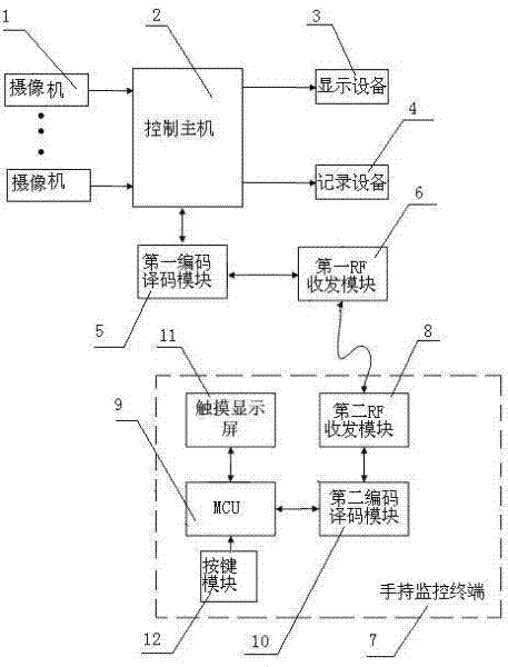
Abstract

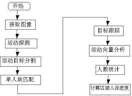
The invention discloses a video passenger flow monitoring system. The system comprises a plurality of cameras, a control host, display equipment, recording equipment, a first coding and decoding module, a first radio frequency (RF) transceiving module and a handheld monitoring terminal, wherein the handheld monitoring terminal comprises a second RF transceiving module, a micro control unit (MCU),a second coding and decoding module, a touch display screen and a key module; and the handheld monitoring terminal receives and displays a passenger flow video transmitted by the control host and calculates passenger flow density. A video passenger flow monitoring method comprises the following steps of: motion detection, moving target segmentation, single block matching, target tracking, motion vector analysis, people counting and regional passenger flow density calculation. The system and the method are used in public places and provide decision basis for operations of safety precaution andthe like; due to the configuration of the handheld monitoring terminal, a patroller can retrieve monitoring videos and calculate the passenger flow density of each region in real time; and therefore,staffing can be performed flexibly and highly effectively and a dangerous case can be handled timely and effectively.

Description

technical field [0001] The invention relates to a passenger flow monitoring system and method, in particular to an intelligent video passenger flow monitoring system and method, belonging to the technical field of video monitoring. Background technique [0002] Video surveillance system is an important part of the security technology system, and video surveillance technology has been widely used in recent years. The video surveillance system can directly watch the situation of the monitored place by controlling the camera and its auxiliary equipment (cloud platform, lens, etc.); at the same time, it can record all or part of the image and sound of the monitored place for future monitoring. The handling of certain events provides convenient conditions and important basis. The video surveillance system can also operate in conjunction with other safety technology prevention systems such as anti-theft, alarm, and fire protection, making the prevention ability stronger, and real...

Claims


Application Information

Patent Timeline
Patent Type & Authority Patents(China)
IPC IPC(8): H04N7/18H04N7/26G06T7/20G06K9/00
Inventor 薛峰刘为
Owner JIANGSU KEDA HUIFENG SCI & TECH
Learn More