
Construction method for underground box culvert of existing railway line

A construction method and existing line technology, applied in earthwork drilling, mining equipment, tunnels, etc., can solve problems affecting jacking construction, affecting box culvert elevation, difficult to control displacement, etc., to speed up construction and ensure line safety Effect

Active Publication Date: 2011-02-02
ZHEJIANG CONSTR ENG GRP CO LTD
View PDF5 Cites 54 Cited by
  • Summary
  • Abstract
  • Description
  • Claims
  • Application Information

AI Technical Summary

Problems solved by technology

[0005] 1. During conventional jacking construction, it is very easy to encounter uncertain underground cables within the existing line range, which will affect the jacking construction, and it is difficult to ensure the safety of cables
[0006] 2. The conventional jacking method cannot set a slide plate in the jacking section, and it is easy to cause head-up and pinching during jacking construction
[0007] 3. The conventional jacking method cannot set a slide plate in the jacking section. During the jacking process, the soil below the box culvert is prone to large settlement, which affects the elevation of the box culvert
[0008] 4. The conventional jacking method cannot set the positioning beam, and it is easy to cause overtop phenomenon during jacking construction, and it is difficult to control its displacement
[0009] 5. The box culvert is directly pushed into the soil by the conventional jacking method, and the waterproof layer is squeezed by the soil during the jacking process, which is easily damaged and cannot be repaired
[0010] 6. The conventional jacking method adopts the method of digging and jacking while jacking, and the soil around the box culvert is disturbed during jacking, which will cause great safety hazards to the existing lines

Method used


Image

  • Construction method for underground box culvert of existing railway line
  • Construction method for underground box culvert of existing railway line
  • Construction method for underground box culvert of existing railway line

Examples


Embodiment Construction

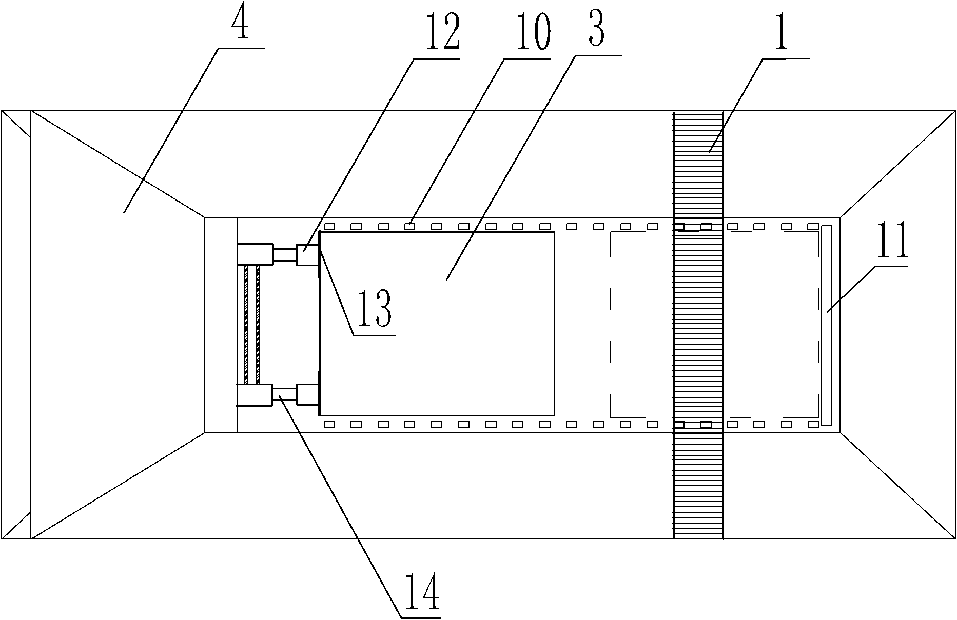
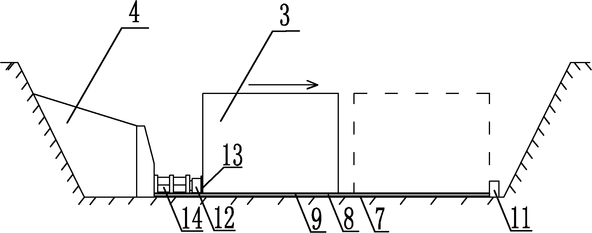
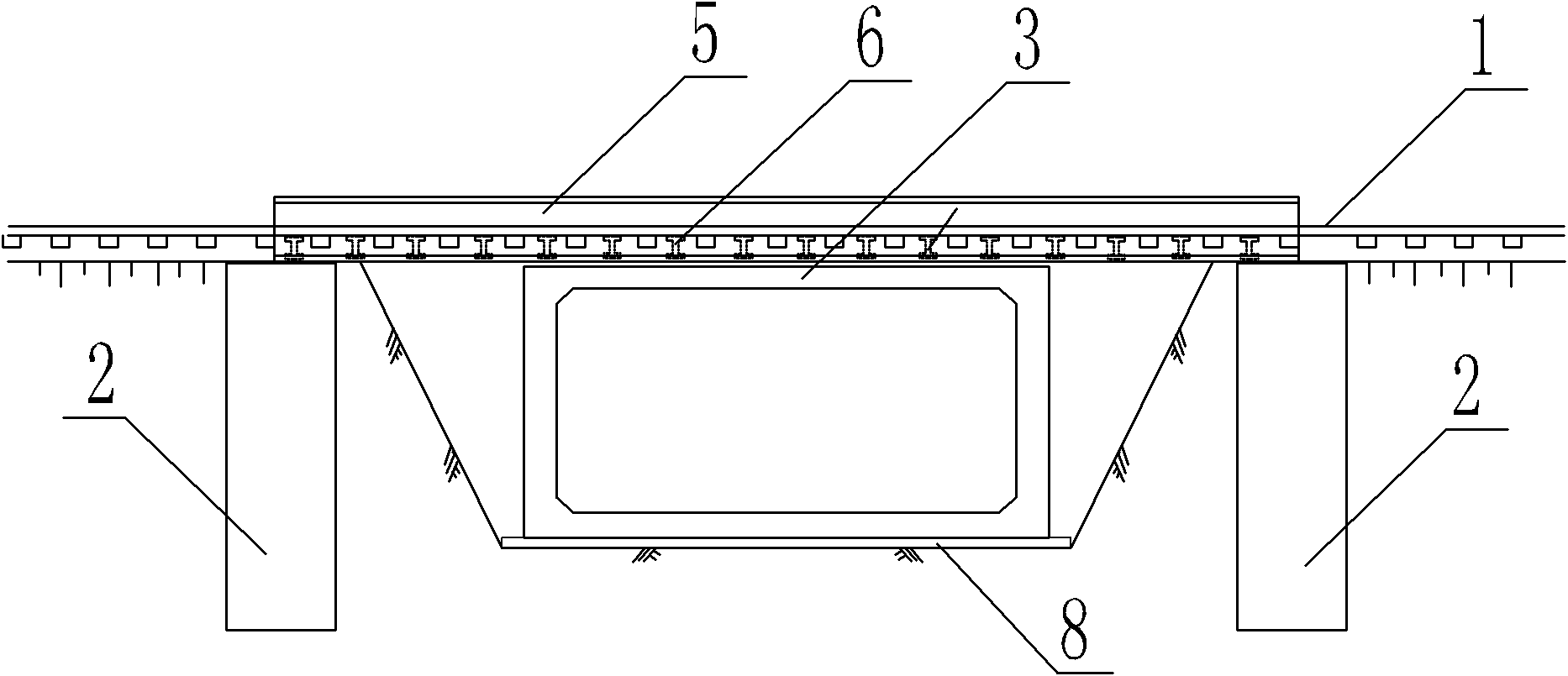
[0051] Such as Figure 1~Figure 3 As shown, the construction method of the underground box culvert of the existing railway line specifically includes the following steps:

[0052] 1. Excavate the earthwork of the beam foundation under the existing railway line 1 and set up a retaining wall, place a steel cage 2, construct a rectangular hole pile with a cross-section of 1.25×1.25m, and the concrete strength is C25, and excavate a working pit at the same time. The working pit adopts soil nailing wall or other support forms for open cut construction. The safe distance between the excavation sideline of the foundation pit near the existing line and the shoulder of the existing subgrade is more than 1.5m.

[0053] 2. Set cushion layer 7 and slide plate 8 in the working pit. Construction isolation layer 9 on the slide. The method of the isolation layer is as follows: waste engine oil and talcum powder are heated and mixed according to the volume ratio of 1:1.5, after pouring and ...


PUM

PropertyMeasurementUnit
Thicknessaaaaaaaaaa
Thicknessaaaaaaaaaa

Abstract

The invention relates to a construction method for an underground box culvert of an existing railway line which is characterized in that a first-dig last-push construction method is adopted; a temporary beam foundation is firstly constructed and a working pit is dug; a D-shaped temporary beam and a cross beam are erected to reinforce the existing railway line; a foundation pit on the jacking section is dug; the box culvert prefabricated in the working pit is integrally jacked by utilizing a hydraulic jack for the back constructed in advance; and the displacement of the box culvert is controlled by a positioning beam. The invention solves the construction difficulties in the prior art, overcomes the phenomena of head raise, head stab, over head and the like of the box culvert during jacking construction, has the advantages of great technical superiority, line safety guarantee and construction speed acceleration, and is suitable for the box culvert construction of underpasses, bridges and culverts of the existing railway underpass line on railway.

Description

technical field [0001] The invention belongs to the field of building construction, in particular to a construction method for an underground box culvert of an existing railway line. Background technique [0002] As the country increases investment in infrastructure construction, a large number of railway projects need to be rebuilt and expanded. During the reconstruction and expansion of the railway, the underground passage (including the entrance and exit tunnel, luggage tunnel, etc.) needs to pass through the existing railway line, but it cannot affect the normal operation of the railway, and the underground passage also needs to be constructed with a waterproof layer on the outer wall and top surface . Since the line is in normal operation and trains are passing as usual, the line cannot be removed. [0003] During the conventional cast-in-place construction, the distance between the top surface of the tunnel box culvert and the rail line is too close, causing great sa...

Claims


Application Information

Patent Timeline
IPC IPC(8): E21D9/00
Inventor 金振饶益民钟将钱昀
Owner ZHEJIANG CONSTR ENG GRP CO LTD
Learn More