Rotary clamping apparatus for drilling crankshaft large disk flange hole

A technology of rotating fixture and crankshaft, applied in boring/drilling, drilling/drilling equipment, clamping and other directions, can solve the problem of easily bumping the crankshaft, achieve reliable fixation and locking, easy drilling processing, structure simple effect

Inactive Publication Date: 2011-02-09
TIANRUN IND TECH CO LTD
View PDF9 Cites 11 Cited by
  • Summary
  • Abstract
  • Description
  • Claims
  • Application Information

AI Technical Summary

Problems solved by technology

In this way, it is easy to damage the crankshaft when the crankshaft is fixed to the fixture vertically from the horizontal position.

Method used


Image

  • Rotary clamping apparatus for drilling crankshaft large disk flange hole
  • Rotary clamping apparatus for drilling crankshaft large disk flange hole
  • Rotary clamping apparatus for drilling crankshaft large disk flange hole

Examples


Embodiment Construction

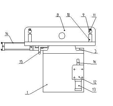
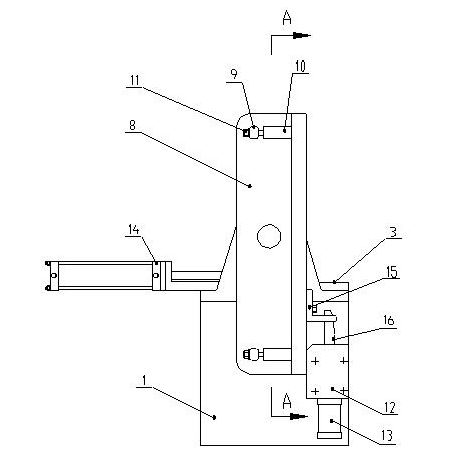
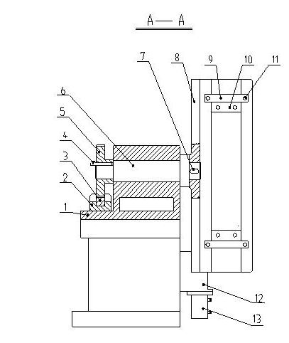
[0015] from figure 1 , figure 2 , image 3 , Figure 4 , Figure 5 It can be seen in the figure that a rotary jig for drilling the flange hole of the crankshaft plate includes a support 1, a rack slide rail 2, a driving cylinder 14, a rack 3, a gear 5, a rotating shaft 6, and a clamp body supporting plate 8. A horizontal circular hole is arranged on the upper part of the support 1, and the rotating shaft 6 is installed in the circular hole of the support 1, and the rotating shaft 6 can rotate in the circular hole. One end of rotating shaft 6 is equipped with gear 5, and the other end is connected and fixed with clamp body supporting plate 8, specifically gear 5 and clamping body supporting plate 8 are fixed on the two ends of rotating shaft 6 by wedge key 4 and flat key 7 respectively. The rack slide rail 2 is fixed on the flat plate at the bottom of the support 1. There is a plane at one end of the rack slide rail 2, and the driving cylinder 14 is fixed on this plane; th...


PUM


Abstract

The invention relates to a rotary clamping apparatus for drilling a crankshaft large disk flange hole. The rotary clamping apparatus comprises a support seat, a rack slideway, a drive cylinder, a rack, a gears, a rotating shaft and a clamping apparatus body supporting plate, wherein the rotating shaft is arranged in a round hole of the support seat; one end of the rotating shaft is provided with the gears, while the other end is connected and fixed with the clamping apparatus body supporting plate; the rack slideway is arranged on a flat plate on the lower part of the support seat; the rack is arranged in the rack slideway and is connected with a cylinder rod of the drive cylinder; the rack and the gears are occluded to drive the rotating shaft to rotate and thus drive the clamping apparatus body supporting plate to roll over so as to ensure that the clamping apparatus body supporting plate is in two position states, namely a horizontal position and a vertical position. The rotary clamping apparatus has a simple structure; a crankshaft is difficult to damage when horizontally clamped; and after being clamped, the crankshaft can rotate to the vertical position to be reliably fixed and locked and is conveniently drilled. The rotary clamping apparatus is an ideal rotary clamping apparatus for drilling the crankshaft large disk flange hole.

Description

technical field [0001] The invention relates to a fixture for crankshaft processing, in particular to a rotary fixture for drilling the flange hole of the crankshaft large disc. Background technique [0002] We know that the drilling of the flange hole of the crankshaft is mostly done by a rocker drill. The crankshaft is placed horizontally during the turnover between the processing steps, but when drilling the crankshaft flange hole on the rocker drill, it is necessary to place the crankshaft flange upwards and fix it vertically on the fixture. In this way, it is easy to damage the crankshaft during the operation from the horizontal position to being vertically fixed on the jig. Contents of the invention [0003] The technical problem to be solved by the present invention is to overcome the deficiencies of the above-mentioned prior art, and provide a simple structure, reliable fixing and locking, the crankshaft is in a horizontal state when clamping, and the crankshaft ...

Claims


Application Information

Patent Timeline
Patent Type & Authority Applications(China)
IPC IPC(8): B23B41/02B23Q3/06
Inventor 孙海涛毕可国丛建臣慈惟红
Owner TIANRUN IND TECH CO LTD
Why Eureka
Try Eureka