
Tool for detecting steel die positioning pin of CRTSIII type track slab

A positioning pin detection and track plate technology, which is applied to measuring devices and instruments, can solve the problems of low detection accuracy and slow detection speed of CRTSⅢ track plate steel mold positioning pins, and achieve simple structure, convenient installation and accurate positioning. Effect

Inactive Publication Date: 2011-11-23
中建铁路建设有限公司 +1
View PDF0 Cites 0 Cited by
  • Summary
  • Abstract
  • Description
  • Claims
  • Application Information

AI Technical Summary

Problems solved by technology

[0003] The purpose of this utility model is to provide a CRTSⅢ track slab steel mold locating pin detection tool to solve the technical problems of CRTSⅢ track slab steel mold locating pin low detection accuracy and slow detection speed

Method used


Image

  • Tool for detecting steel die positioning pin of CRTSIII type track slab
  • Tool for detecting steel die positioning pin of CRTSIII type track slab
  • Tool for detecting steel die positioning pin of CRTSIII type track slab

Examples


Embodiment Construction

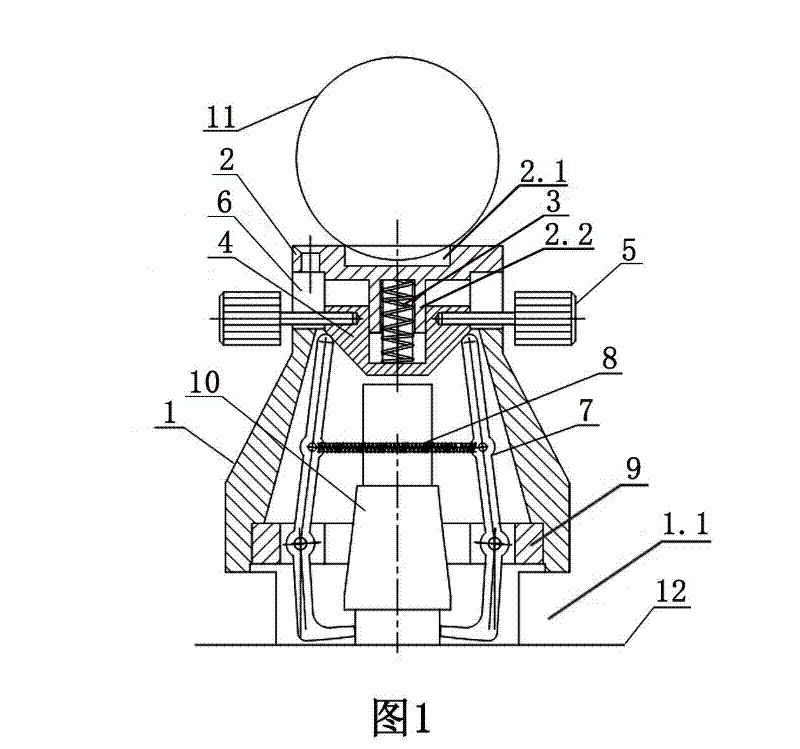
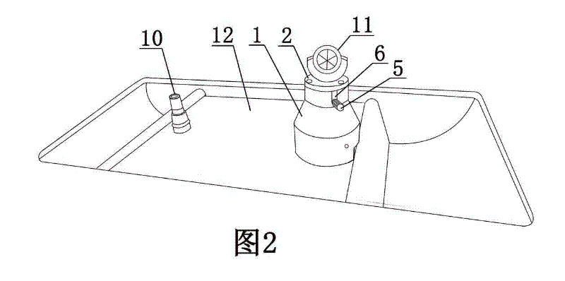
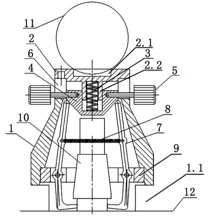
[0016] Examples see figure 1 As shown, this CRTSⅢ type track plate steel mold positioning pin detection tool includes a fixed cylinder seat. The fixed cylinder seat 1 is a cylindrical structure with a thin upper part and a thicker bottom. The bottom surface of the fixed cylinder seat is located on the slope surface 12 On both sides of the bottom of the fixed cylinder seat 1, bayonets 1.1 can be provided, and the bayonets can be close to the raised part on the edge of the slope at the bottom of the rail, which can also reduce the overall weight. The top of the fixed cylinder seat 1 is connected with a top cover 2 by screws, and the center of the upper surface of the top cover has a ball prism installation groove 2.1, and the ball prism 11 is installed in the ball prism installation groove, and the center of the bottom surface of the top cover is connected with a compression spring positioning sleeve 2.2 .

[0017] A handle bar for fixing the positioning pin, an inverted cone ...


PUM


Abstract

The invention discloses a tool for detecting a steel die positioning pin of a CRTSIII type track slab. The top of a fixed cylinder base is connected with a top cover; a prismosphere mounting groove is arranged in the center of the upper surface of the top cover; a prismosphere is mounted in the prismosphere moutnign groove; a downward-protruded pressure spring positioning sleeve is arranged in the center of the lower surface of the top cover; a gripping rod for fixing the positing pin, an inverse cone body and the pressure spring are arranged inside the fixed cylinder base; a groove is arranged in the center of the inverse cone body; a pressure spring positioning sleeve is arranged in the groove of the inverse cone body; the upper part of the pressure spring is arranged in the pressure spring positioning sleeve; the lower part of the pressure spring is arranged in the groove of the inverse cone body; a slot hole corresponding to the length of the pressure spring positioning sleeve is arranged on the side wall of the fixed cylinder base; a connecting rod of a hand wheel connecting rod passes through the slot hole and is connected with the upper part of the side wall of the inverse cone body; a gripper at the lower end of the gripping rod surrounds the root part of the positioning pin; and the top end of the gripping rod is connected with the conical surface of the outer side wall of the inverse cone body in the mode of sliding contact. The tool can be used for converting the deviation of the steel die positioning pin of the track slab into the deviation of the center of a prism and has the advantages of simple structure, convenience in installation and accuracy in positioning.

Description

technical field [0001] The utility model relates to a detection tool for steel mold positioning pins of railway track slabs. Background technique [0002] CRTSⅢ type track slab is a new type of track slab for railway passenger dedicated line. The deviation of CRTSⅢ type track slab steel mold positioning pin and the position deviation of embedded casing are important indicators to determine whether the finished CRTSⅢ type track slab is qualified. The positioning pin of the high-precision track slab steel mold is a necessary condition for the high-precision track slab embedded casing, so it is necessary to carry out precise inspection on the track slab steel mold locating pin during the track slab production process to ensure that the finished slab embedded casing the quality of. However, the high-precision detection of CRTSⅢ type track plate steel mold positioning pins cannot be completed by conventional measuring tools due to improper operation or lack of benchmarks. If t...

Claims


Application Information

Patent Timeline
Patent Type & Authority Patents(China)
IPC IPC(8): G01B21/00
Inventor 徐细军马志明杨光张晓江
Owner 中建铁路建设有限公司
Learn More