
Transmission and motor vehicle

A technology for transmissions and motor vehicles, which is applied in the directions of transmissions, mechanical equipment, transmission parts, etc., and can solve problems such as inability to achieve installation.

Pending Publication Date: 2020-06-19
ZF FRIEDRICHSHAFEN AG
View PDF0 Cites 0 Cited by
  • Summary
  • Abstract
  • Description
  • Claims
  • Application Information

AI Technical Summary

Problems solved by technology

In particular, it is not possible to mount components that are axially movable

Method used


Image

  • Transmission and motor vehicle
  • Transmission and motor vehicle

Examples


Embodiment Construction

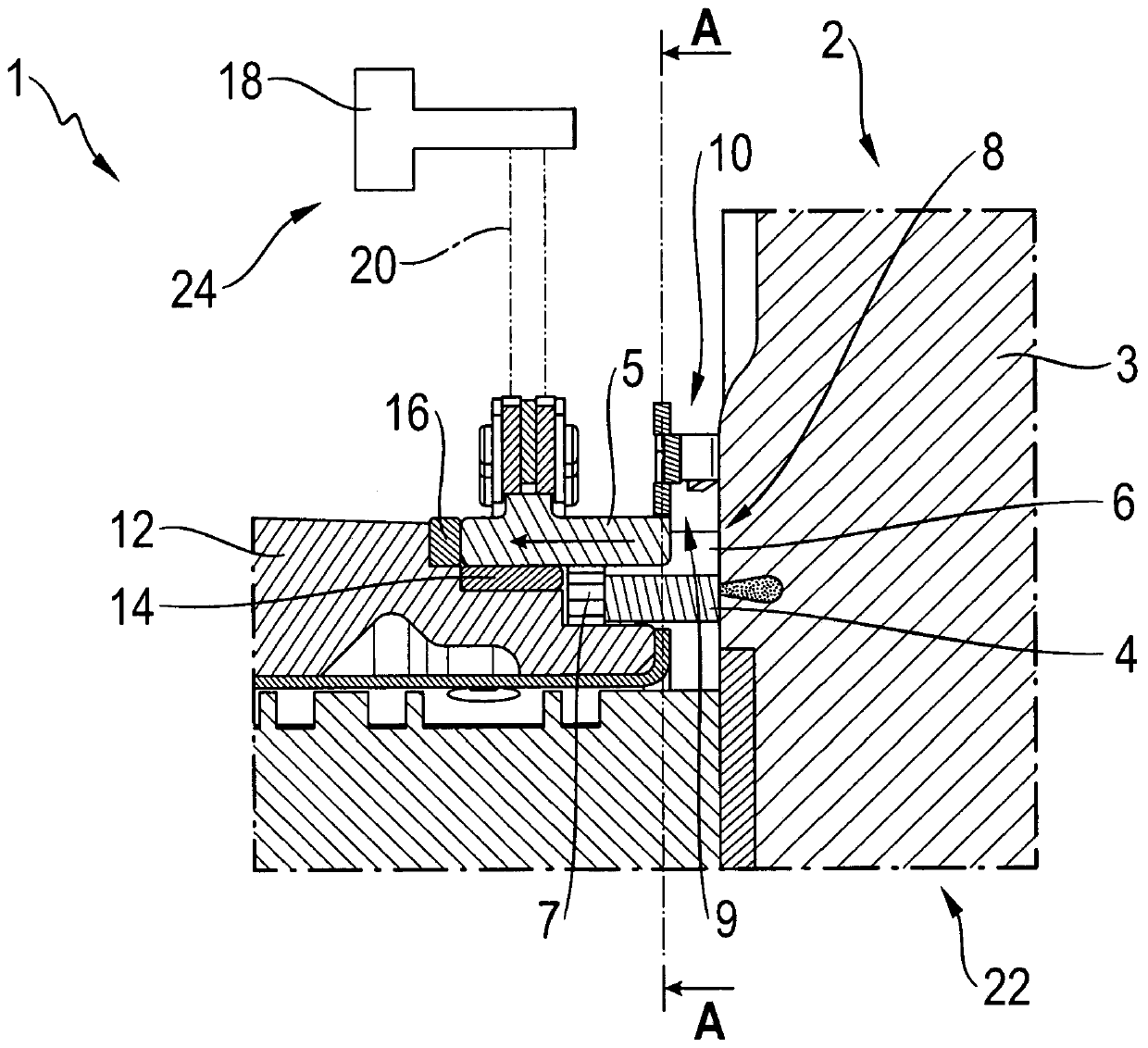
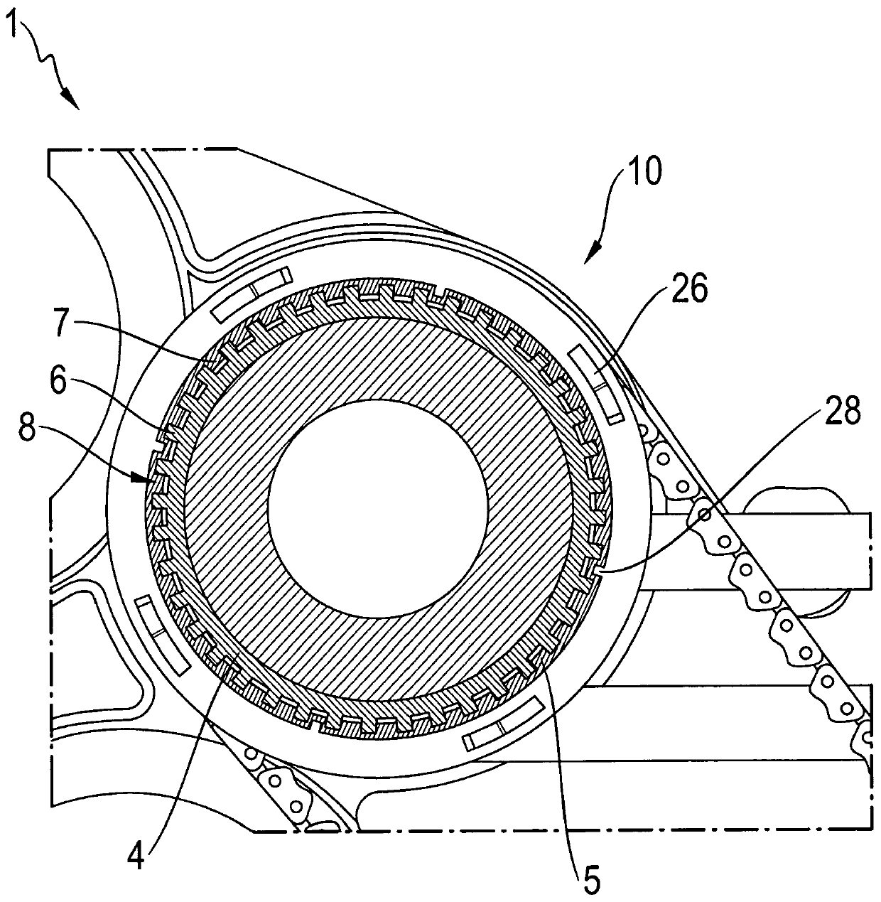
[0027] figure 1 A partial view of the transmission 1 is shown, more precisely in the region of the clutch pack 2 . A gear wheel 4 is welded to the housing 3 of the clutch assembly 2 , which engages with the sprocket 5 . In this case, the gear wheel 4 has an external toothing 6 and the sprocket 5 has an internal toothing 7 , via which the toothed wheel and the sprocket are in engagement with one another.

[0028] The gear 4 is preferably fixedly welded or fixed to the housing in any other way. Due to the fact that the sprocket and the gear wheel 4 are axially movable to one another via a toothed connection 8 , the sprocket can move freely due to the air gap 9 between the housing 3 and the sprocket 5 . In order to achieve a fixed positioning of the sprocket 5, a pretensioning device 10 is provided. The pretensioner is figure 1 In the refinement shown in , it is fastened to the housing and moves the sprocket away from the housing 3 . Alternatively, the pretensioning device c...


PUM


Abstract

The invention relates to a transmission for a motor vehicle. The transmission comprises a chain, a drive member assembly driven by the chain, a driven member assembly driven by the chain, at least onechain wheel as part of the drive member assembly or the driven member assembly, and an axially movable member located axially next to the chain wheel. The transmission is characterized in that the chain wheel is supported on the axially movable member by means of a pre-tensioning device. The invention further relates to a motor vehicle.

Description

technical field [0001] The invention relates to a transmission for a motor vehicle having a chain, a drive member assembly driven via the chain and a driven member assembly driven via the chain, at least one A sprocket and an axially movable member located beside the sprocket in the axial direction. Background technique [0002] Due to the ever-increasing component density in motor vehicles, it is also necessary to arrange individual components spatially separated from one another. Therefore, in order to connect these components to each other via a certain route, it is also known to connect these components by means of chains. An electric motor used as a second drive unit can be connected, for example via a chain, to the rest of the drive train and thus drive the motor vehicle. [0003] In addition, however, the chain can also be used to drive auxiliary units, such as pumps. [0004] In all cases, the chain connection is a critical connection, since the oblique position o...

Claims


Application Information

Patent Timeline
IPC IPC(8): F16H9/24F16H55/30F16H57/021F16H57/023F16H57/035
CPCF16H9/24F16H55/303F16H57/021F16H57/023F16H57/035F16H55/30F16H7/06F16H57/0025
Inventor N·茨韦格U·菲尔茨拉夫A·艾伯特
Owner ZF FRIEDRICHSHAFEN AG
Learn More