
Self-adjusting electric power mechanism suite

A self-adjusting and kitting technology, applied in the field of electric power, can solve the problems of no way to deal with external fire, short circuit of power components, poor heat dissipation effect, etc., to improve the ability of self-protection, reduce the probability of fire, and be easy to replace.

Pending Publication Date: 2021-10-08
金刚
View PDF0 Cites 0 Cited by
  • Summary
  • Abstract
  • Description
  • Claims
  • Application Information

AI Technical Summary

Problems solved by technology

[0004] Aiming at the deficiencies of the prior art, the present invention provides a self-regulating power mechanism kit, which solves the problems of poor external airflow adjustment and internal heat dissipation, and no way to deal with external fire and short circuit of power components

Method used


Image

  • Self-adjusting electric power mechanism suite
  • Self-adjusting electric power mechanism suite
  • Self-adjusting electric power mechanism suite

Examples


Embodiment example 1

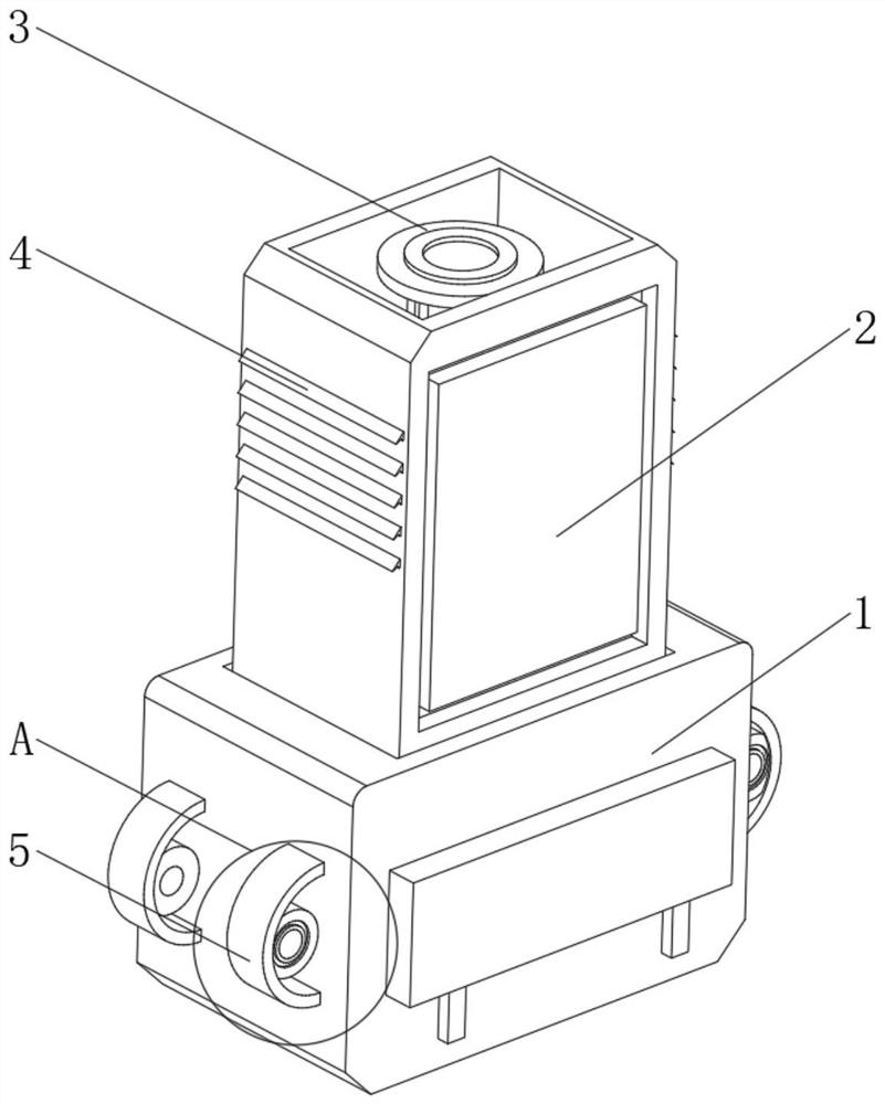
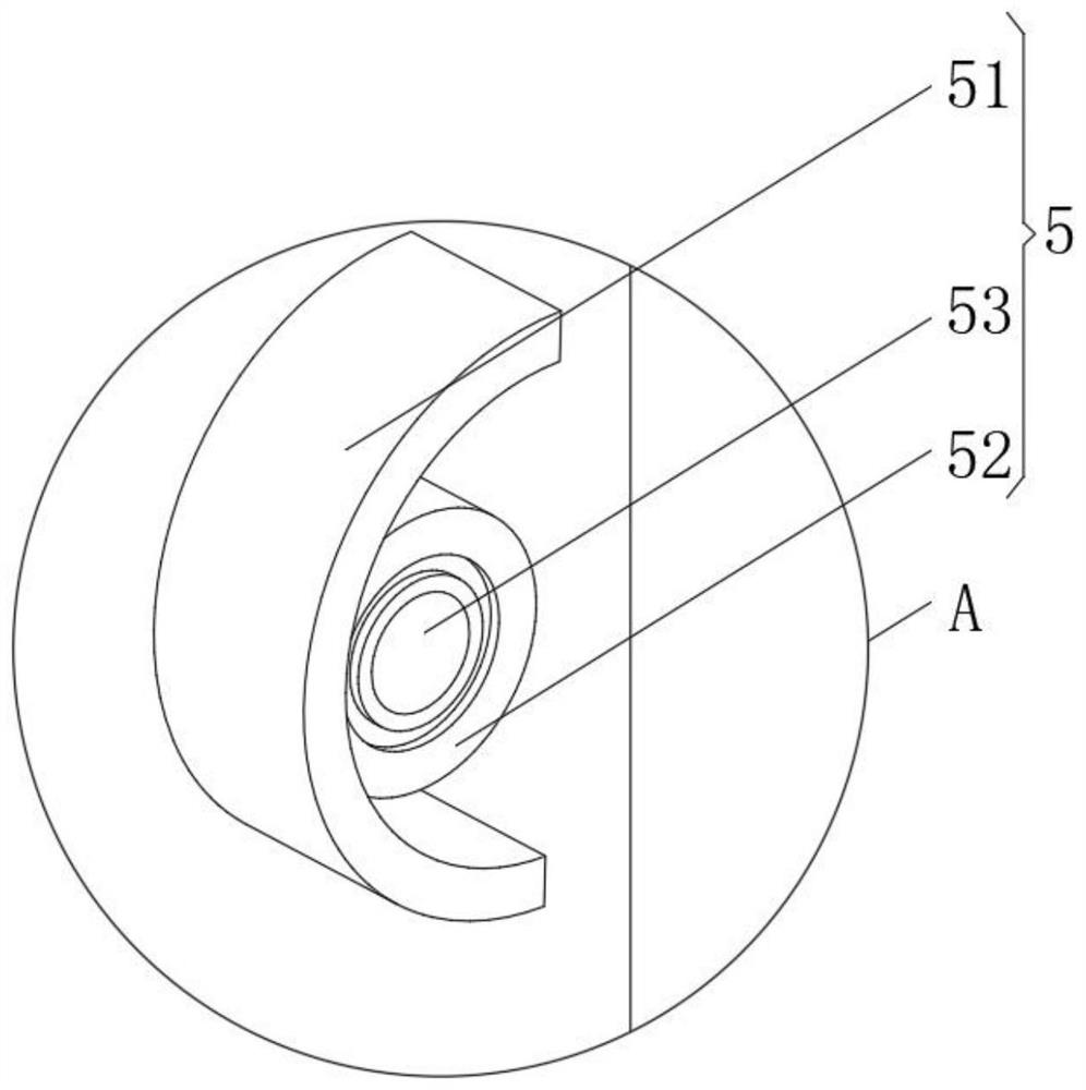
[0033] see Figure 1-4 , the present invention provides a technical solution: a self-regulating power mechanism kit, specifically including,

[0034] Kit base 1, the kit base 1 has an inner cavity mounting base body, and an inner cavity for installing the kit;

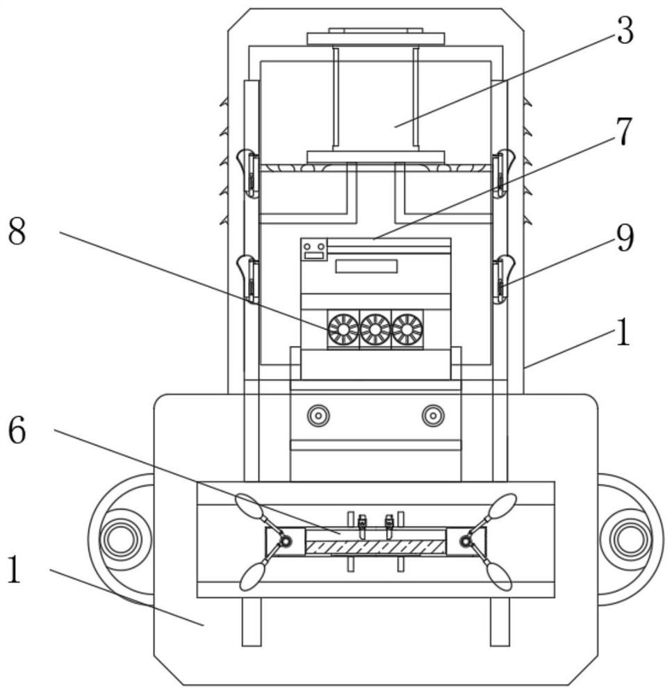
[0035] Kit body 2, the kit body 2 has an installation box, and a docking seat 3 installed above the kit body 2, a docking cavity is opened in the middle of the docking seat 3, and a spring buckle is arranged inside the docking cavity, and the side of the kit body 2 A heat dissipation grid 4 is provided to facilitate the installation of the top kit inside the docking seat 3, and the spring docking buckle can ensure the positioning and fixing of the device;

[0036] Exhaust device 9, this exhaust device 9 has adjustment mechanism, and is installed on the installation buckle frame of kit main body 2 sides, kit main body 2 internal heat dissipation mechanism suite 7, and heat dissipation mechanism suite 7 is equipped with...

Embodiment example 2

[0042] On the basis of implementing Case 1, please refer to Figure 5-6 , the present invention provides a technical solution: the emergency heat dissipation device 6 includes an integral component box 61 and an external heat conduction sheet 66, the integral component box 61 is installed above the external heat conduction sheet 66, and heat conduction seats 62 are arranged at both ends of the integral component box 61 to conduct heat The outer side of the seat 62 is equipped with an elliptical extended heat conduction sheet 64 through a heat conduction pipe 63, and the elliptical extended heat conduction sheet 64 is arranged above the outer connection heat conduction sheet 66, and a heat conduction gasket is arranged between the outer connection heat conduction sheet 66 and the outer connection heat conduction sheet 66, which can The heat inside the power kit is conducted to the larger external heat conducting fins 66 to increase the heat dissipation area and improve heat exch...


PUM


Abstract

The invention discloses a self-adjusting electric power mechanism suite, which specifically comprises a suite pedestal which is provided with an inner cavity installation pedestal body and an internal cavity for installing the suite; and a suite main body, wherein the suite main body is provided with an installation box body and a butt joint base installed above the suite main body, a butt joint cavity is formed in the middle of the butt joint base, a spring buckle is arranged in the butt joint cavity, and heat dissipation grids are arranged on the side of the suite main body, so that the suite at the top can be conveniently installed in the butt joint base, and the positioning and the fixation of the device can be ensured by adopting the spring butt-joint buckle. The invention relates to the technical field of electric power. The self-adjusting electric power mechanism suite solves the problems that the internal heat dissipation effect of external airflow adjustment is poor, external fire behaviors and short circuit of electric power elements cannot be handled, can be used for monitoring internal heat and also can be handled with high temperature of the external fire behaviors, the self-protection capability of the electric power components is improved, and the risk and loss of the fire hazards are reduced.

Description

technical field [0001] The invention relates to the field of electric power technology, in particular to a self-regulating electric power mechanism kit. Background technique [0002] Power cabinets are often used in power distribution. They are mainly used to install electronic components. Because the electronic components in the power cabinets generate high heat during operation, some power cabinets are equipped with heat dissipation mechanisms to ensure that the electronic components inside The components can operate normally. The heat dissipation mechanism in the existing power cabinet is mainly driven by the heat dissipation motor to rotate the heat dissipation fan, so as to discharge the heat in the power cabinet and reduce the temperature. There is no way to deal with the external fire and the large amount of heat generated by the short circuit of the power components, which is easy to cause large-scale losses. Contents of the invention [0003] (1) Solved technical...

Claims


Application Information

Patent Timeline
Patent Type & Authority Applications(China)
IPC IPC(8): H02B1/56A62C3/16H02B1/50H02B1/46H02B1/48H02B1/28
CPCH02B1/565A62C3/16H02B1/50H02B1/46H02B1/48H02B1/28
Inventor 金刚
Owner 金刚
Learn More