
Welding workbench

A technology of workbench and connecting part, which is applied in the direction of welding equipment, auxiliary welding equipment, welding/cutting auxiliary equipment, etc., can solve the problems that the positioning pin cannot be inserted into the positioning hole, affect the welding effect of the workpiece, and the position deviation of the turning frame, etc., to achieve Guaranteed welding fixing effect, good positioning and fixing effect, and guaranteed fixing position effect

Pending Publication Date: 2021-10-15
ZHEJIANG KIN SHINE TECH
View PDF11 Cites 0 Cited by
  • Summary
  • Abstract
  • Description
  • Claims
  • Application Information

AI Technical Summary

Problems solved by technology

[0004] The above-mentioned solution for maintaining the position of the overturn frame has the following defects: if the difference between the outer diameter of the locating pin and the inner diameter of the locating hole is small, the locating pin cannot be inserted into the locating hole; if the outer diameter of the locating pin and the locating hole If the inner diameter difference is large, there will be a gap between the positioning pin and the positioning pin, and the flipping frame may be turned slightly, which will affect the welding effect of the subsequent workpiece; and if the flipping frame is large and heavy, the positioning pin may be bent , the position of the overturning frame will deviate, which will affect the welding effect of the workpiece

Method used


Image

  • Welding workbench
  • Welding workbench
  • Welding workbench

Examples


Embodiment Construction

[0025] The present invention will be further described below according to the accompanying drawings and specific embodiments.

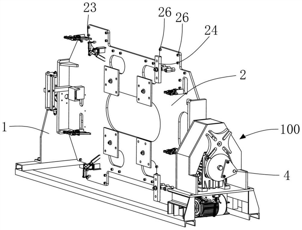
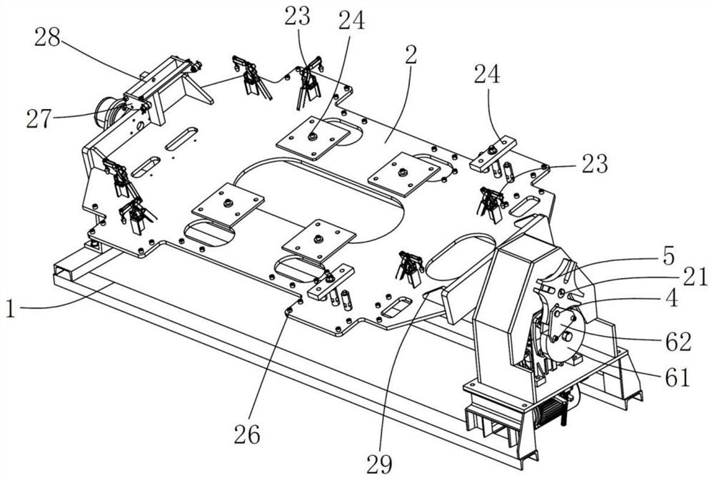
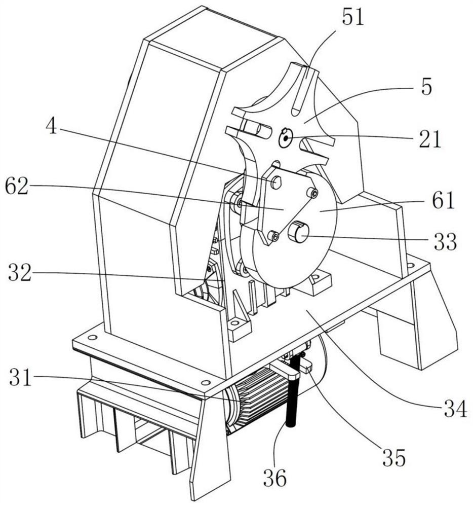
[0026] Depend on figure 1 , image 3 , Figure 4 and Figure 5 As shown, a welding workbench includes a fixed frame 1 and an overturning frame 2 rotatably fixed on the fixed frame 1. The overturning frame 2 and the driver with self-locking function are connected through a linkage mechanism 100. The driver includes a motor 31 and a deceleration Box 32 , the output shaft 33 of the reduction box 32 is linked with the second transmission member 4 , and the axis of the output shaft 33 of the reduction box 32 is located directly below the rotation axis of the reversing frame 2 .

[0027] The input shaft of the reduction box 32 and the rotor shaft of the motor 31 are driven by a belt or a chain. The reduction box 32 and the motor 31 are respectively located on the upper and lower sides of the mounting plate 34. The front side of the motor 31 is hinged and...


PUM


Abstract

The invention relates to a welding workbench. The welding workbench comprises a fixing frame and an overturning frame rotationally fixed to the fixing frame, the overturning frame is connected with a driver with a self-locking function through a linkage mechanism, the linkage mechanism comprises a first transmission part and a second transmission part, the first transmission part and the overturning frame are coaxially and rotationally fixed, the first transmission part is provided with multiple linkage grooves which are annularly and evenly arranged at intervals and used for allowing the second transmission part to stretch inside, the linkage grooves are arranged in the radial direction of the first transmission part and penetrate through the circumferential outer wall of the first transmission part, and the second transmission part can stretch into the linkage grooves or be disengaged from the interiors of the linkage grooves under the action of the driver. The welding workbench has the advantages that the positioning and fixing effects on the overturning frame are better, the subsequent welding and fixing effects of workpieces can be better guaranteed, the workpieces are more convenient to assemble and weld, and the production efficiency can be improved.

Description

technical field [0001] The invention relates to a welding workbench. Background technique [0002] The welding workbench is used to clamp and fix the workpiece, so as to facilitate the subsequent welding of the workpiece with the welding robot. First place the workpiece on the rotatable overturn frame of the welding workbench, and then fix the workpiece on the overturn frame by locking bolts, pressure plates and quick clamping tools. When the workpiece is welded, it is necessary to turn over the overturning frame so that the overturning frame is in a horizontal or vertical state and keep the position of the overturning frame. [0003] For example, in the welding workbench disclosed in the Chinese patent with the application number 201721711639.6, a positioning hole is provided at the edge of the overturn frame, and an axially movable positioning pin is arranged on the fixed part (fixed frame). The rotation axis of the frame is arranged parallel or vertically, and the posit...

Claims


Application Information

Patent Timeline
Patent Type & Authority Applications(China)
IPC IPC(8): B23K37/04B23K37/047
CPCB23K37/0461B23K37/047
Inventor 王岘峰周海峰李晗程勤民
Owner ZHEJIANG KIN SHINE TECH
Learn More