Buried pipe stretcher

A tensioner, buried pipe technology, applied in the direction of pipe elements, pipes/pipe joints/pipes, expansion compensation devices for pipelines, etc., can solve the problem of crack running water, inconsistent settlement of buried pipes, buried pipes deformation and other problems, to ensure the effect of normal use

Inactive Publication Date: 2011-02-09
天津百思特环保能源开发有限公司
View PDF5 Cites 4 Cited by
  • Summary
  • Abstract
  • Description
  • Claims
  • Application Information

AI Technical Summary

Problems solved by technology

Especially since the buildings are piled first and then the buildings are built, it is easy to cause the settlement of the building and the buried pipe to be inconsistent, that is, the settlement of the building body is small, and the settlement of the buried pipe is large, resulting in the stretching of the buried pipe. , when the stretching amount reaches a certain value, it is easy to cause the deformation of the buried pipe, so that the pipe is twisted, stretched, cracked, leaked, or even broken, which seriously affects the normal use of the ground source heat pump.
Even if remedial measures are taken, that is, to dig out the surface soil, find the place where the buried pipe leaks and then remedy it, but it is laborious and laborious, and it cannot guarantee good operation in the future.

Method used


Image

  • Buried pipe stretcher
  • Buried pipe stretcher
  • Buried pipe stretcher

Examples


Embodiment 1

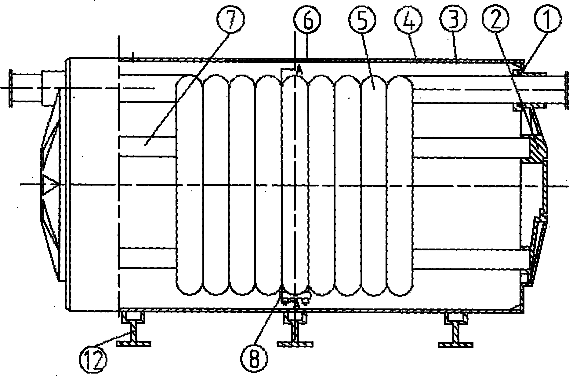
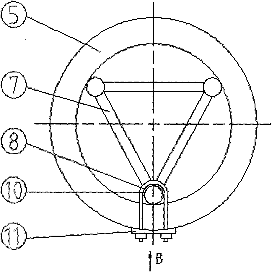
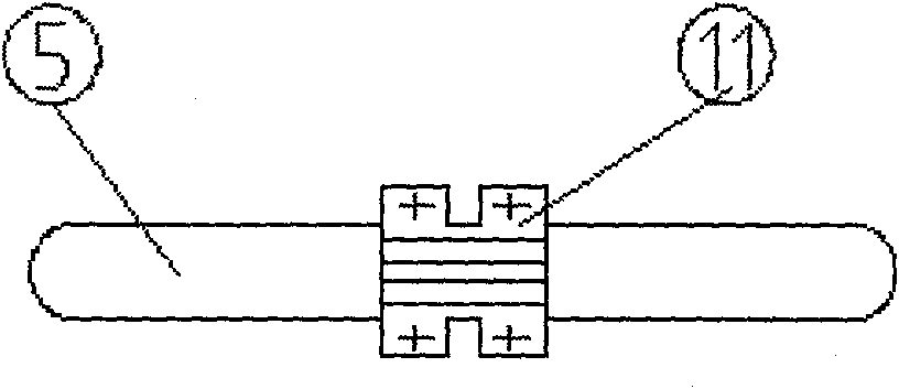
[0026] Embodiment 1: A kind of tensioner for buried pipe, it is set on the bracket 7 of equilateral triangular light non-metallic material with the coil pipe 5 of the same material as the buried pipe, and the center point of the column of the bracket 7 is respectively set with two U U-shaped bolts 8, two U-shaped bolts 8 pass through the gap between the center points of two adjacent coils 5, the fixing plate 11 fixes the two U-shaped bolts 8, and the coiled pipe 5 and the bracket 7 are also fixed; the coiled pipe 5 and the U-shaped A rubber pad 10 is provided between the type bolts 8, and the fixed bracket 7 and the coil 5 are put into the cylinder 4, and the two ends of the bracket 7 are respectively inserted into the pin holes of the end cover 2 at both ends of the cylinder 4, and the end cover 2. It is fixed on both ends of the cylinder 4 and fixed by bolts. The two ends of the coil 5 extend out of the cylinder 4 through the holes at both ends of the cylinder respectively. A...

Embodiment 2

[0027] Embodiment 2: A kind of tensioner for buried pipe, which is set on the upper end of the support column 7 of equilateral triangular light non-metallic material and the coil pipe 5 of the same material as the buried pipe, and the inner wall of U-bolt 8 is welded and fixed Steel strips 9, U-shaped bolts 8 are set on the upper end of the coil pipe 5, holes are opened on the upper end of the support column 7, the U-shaped bolts 8 are inserted into the holes of the support column 7, and fixed with the coil pipe 5, between the coil pipe 5 and the steel strip 9 There is a rubber pad 10, the fixed bracket 7 and the coil 5 are placed in the cylinder 4, the end caps 2 are respectively fixed on both ends of the cylinder 4, and the two ends of the bracket 7 are respectively inserted into the pin holes in the end cap 2 , the two ends of the coil 5 protrude through the holes at both ends of the cylinder 4 respectively, and the sealing shaft 1 is provided between the coil 5 and the end ...


PUM


Abstract

The invention belongs to a buried pipe compensating device, in particular relates to a buried pipe stretcher. A coil pipe is sleeved to and fixed to an upright post of a bracket which is arranged in a cylinder together with the coil pipe, end covers are respectively fixed at both ends of the cylinder, both ends of the bracket are respectively inserted in pin shaft holes in the end covers, and both ends of the coil pipe respectively extend out from both end holes of the cylinder. The invention has the advantages that the stretching problem of the buried pipe can be thoroughly solved by compensating the stretched buried pipe with the stretcher so as to prevent a pipeline from being twisted, stretched to be deformed, cracked to run water or even broken because of the stretching and the deformation of the buried pipe in the service life of a ground source heat pump and ensure the normal use of the buried pipe.

Description

technical field [0001] The invention belongs to a buried pipe compensation device, in particular to a buried pipe tensioner. Background technique [0002] With the maturity of ground source heat pump technology and the development in China in the past ten years, it has begun to be gradually used in actual production and life. From the perspective of distribution, most of them are in the inland or coastal areas, but these areas are rocky or conventional. Areas with good soil and other geological conditions. [0003] With the global warming and the introduction of national energy conservation and emission reduction policies, the use of ground source heat pumps is becoming more and more popular, and soft soil subsidence generally occurs near the piers or beaches formed by artificial dredging in Tianjin Port. The characteristics of this kind of ground are: the ground surface is slightly higher than sea level, and the groundwater resources are very rich and complex, even includi...

Claims


Application Information

Patent Timeline
Patent Type & Authority Applications(China)
IPC IPC(8): F16L51/00
Inventor 刘云堂
Owner 天津百思特环保能源开发有限公司
Why Eureka
Try Eureka