High-power density permanent magnet motor

A high power density, permanent magnet motor technology, applied in the direction of electrical components, electromechanical devices, electric components, etc., can solve the problems of low motor efficiency and thrust density, poor sine degree of air gap flux density waveform, high motor vibration and noise, etc. Achieve the effect of large electromagnetic thrust, good sine degree and small thrust fluctuation

Active Publication Date: 2011-02-09
HARBIN INST OF TECH
View PDF10 Cites 15 Cited by
  • Summary
  • Abstract
  • Description
  • Claims
  • Application Information

AI Technical Summary

Problems solved by technology

[0004] The purpose of the present invention is to solve the problem of low air-gap flux density and poor sine degree of the air-gap flux density waveform of the traditional double-sided coreless linear permanent magnet synchronous motor, so the efficiency and thrust density of the motor are low, the thrust fluctuation is large, the vibration and vibration of the motor The problem of high noise, therefore, the present invention provides a high power density permanent magnet motor

Method used


Image

  • High-power density permanent magnet motor
  • High-power density permanent magnet motor
  • High-power density permanent magnet motor

Examples


specific Embodiment approach 1

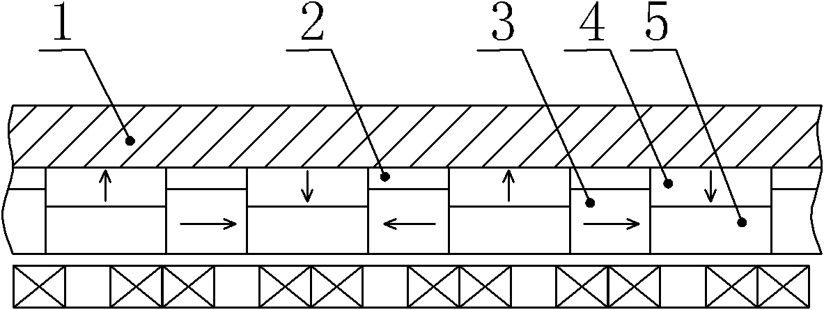
[0022] Specific implementation mode one: the following combination figure 1 Describe this embodiment, the high power density permanent magnet motor of this embodiment, it is flat linear permanent magnet motor with unilateral structure: it includes primary and secondary, there is an air gap between primary and secondary, and secondary includes yoke plate 1. m spacer magnets 2, m auxiliary permanent magnets 3, m main permanent magnets 4 and m concentrating magnets 5, the yoke plate 1 is flat, and main Permanent magnet 4 and spacer magnet 2, the inboard of main permanent magnet 4 is provided with concentrating magnet 5, and concentrating magnet 5 is identical with main permanent magnet 4 along the moving direction width; The permanent magnets 3 have the same width along the moving direction; the outer surfaces of the m auxiliary permanent magnets 3 and the m collecting magnets 5 are on the same plane, and the main permanent magnets 4 are magnetized in parallel, and the magnetizi...

specific Embodiment approach 2

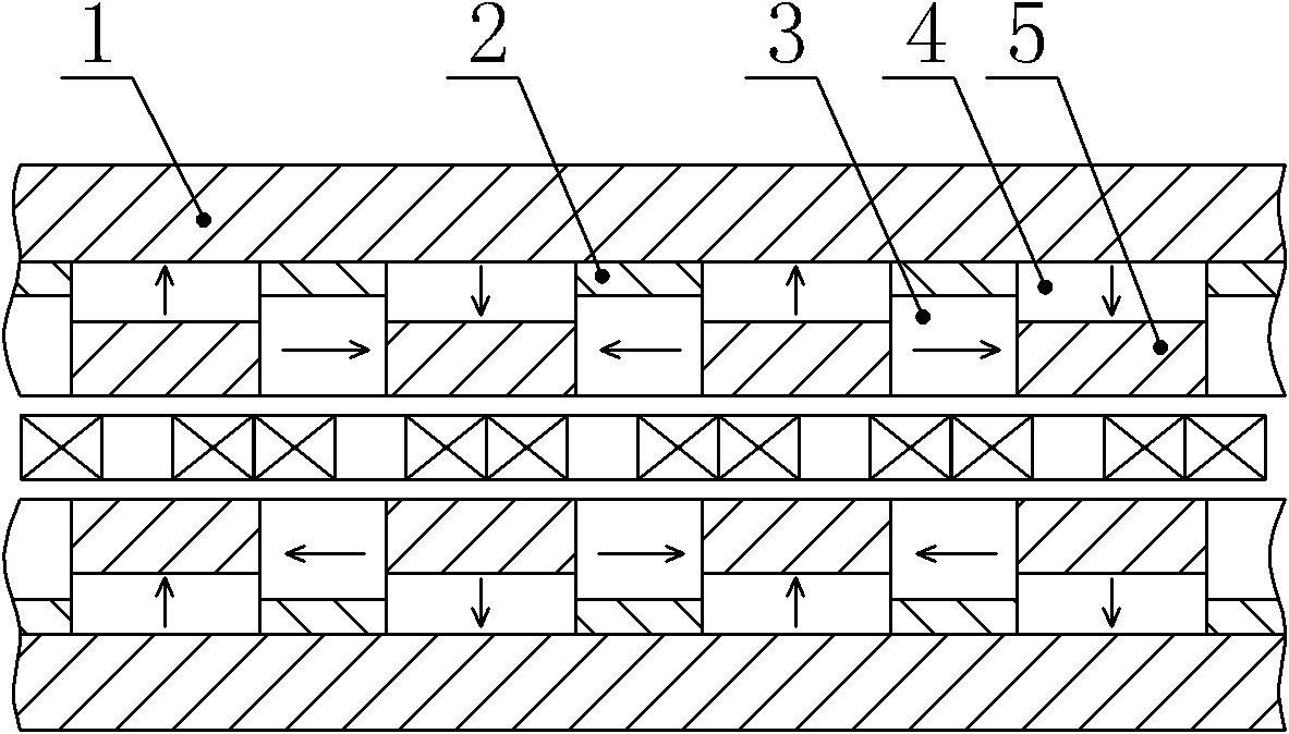
[0026] Specific implementation mode two: the following combination figure 2 Describe this embodiment, the high power density permanent magnet motor of this embodiment, it is the flat linear permanent magnet motor of double-sided structure:

[0027] It includes a primary and two secondary, with an air gap between the primary and each secondary, and each secondary includes a yoke plate 1, m spacer magnets 2, m auxiliary permanent magnets 3, and m main permanent magnets 4 And m pieces of concentrating magnets 5, yoke plate 1 is a flat plate, on the inner side wall of yoke plate 1, main permanent magnet 4 and spacer magnet 2 are successively arranged at intervals, the inboard of main permanent magnet 4 is provided with concentrating magnets 5, concentrating magnets 5 and The main permanent magnet 4 has the same width along the moving direction; the auxiliary permanent magnet 3 is set on the inner side of the spacer magnet 2, and the spacer magnet 2 and the auxiliary permanent mag...

specific Embodiment approach 3

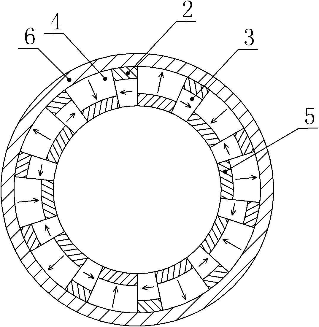
[0031] Specific implementation mode three: the following combination image 3 Describe this embodiment, the high power density permanent magnet motor of this embodiment, it is the cylindrical permanent magnet motor of outer rotor structure:

[0032] It includes a stator and a rotor. The rotor is located outside the stator. There is an air gap between the stator and the rotor. The rotor includes a yoke tube 6, m spacer magnets 2, m auxiliary permanent magnets 3, m main permanent magnets 4 and m concentrator magnets. 5. The yoke barrel 6 is cylindrical, and the main permanent magnet 4 and the spacer magnet 2 are arranged at intervals in sequence on the inner surface of the yoke barrel 6. The inner side of the main permanent magnet 4 is arranged with a concentrating magnet 5, and the concentrating magnet 5 and the main permanent magnet 4 The angle along the circumferential direction is the same; the auxiliary permanent magnet 3 is arranged inside the spacer magnet 2, and the spac...


PUM


Abstract

The invention relates to a high-power density permanent magnet motor belonging to the field of motors. The invention solves the problems of low efficiency and thrust density, large thrust fluctuation and high vibration and noises of the traditional double-edge ironless straight line permanent magnet synchronous motor, which are caused by low air gap magnetic density and poor sine degree of air gap magnetic density wave forms. An air gap is positioned between a primary pole and a secondary pole of a straight line motor; main permanent magnets and isolated magnets are sequentially arranged on the inner wall of a yoke plate at intervals; the inner sides of the main permanent magnets are provided with assembling magnets which have same widths along a motion direction; the inner sides of the isolated magnets are provided with auxiliary permanent magnets which have same widths along the motion direction; the outer side surfaces of m auxiliary permanent magnets and m assembling magnets are positioned on a same plane; the main permanent magnets are parallelly magnetized in magnetizing directions perpendicular to the motion directions of active cells, and every two adjacent main permanent magnets are in reverse magnetizing directions; the auxiliary permanent magnets are parallelly magnetized in the magnetizing directions parallel to the motion directions of the active cells, and every two adjacent auxiliary permanent magnets are in reverse magnetizing directions.

Description

technical field [0001] The invention relates to a high power density permanent magnet motor, which belongs to the field of motors. Background technique [0002] Figure 6 Shown is a schematic structural diagram of a traditional double-sided coreless linear permanent magnet synchronous motor. The secondary of the motor is composed of a yoke plate and a flat permanent magnet. The permanent magnets are magnetized parallel to the direction perpendicular to the direction of motion. The permanent magnets are magnetized in the same direction, with the primary located between the two secondary plates. The normal component of the magnetic force line generated by the permanent magnet passes through the primary vertically, and the energized primary winding interacts with the magnetic field of the secondary permanent magnet to generate electromagnetic force and push the mover to move in a straight line. [0003] However, the linear motor has the following disadvantages: the air-gap fl...

Claims


Application Information

Patent Timeline
Patent Type & Authority Applications(China)
IPC IPC(8): H02K41/03
Inventor 寇宝泉曹海川赵斌超
Owner HARBIN INST OF TECH
Why Eureka
Try Eureka