Vehicle travel support device, vehicle, and vehicle travel support program

A technology for vehicle driving and auxiliary devices, which is used in control devices, vehicle components, vehicle safety arrangements, etc.

Inactive Publication Date: 2011-02-09
HONDA MOTOR CO LTD
View PDF13 Cites 26 Cited by
  • Summary
  • Abstract
  • Description
  • Claims
  • Application Information

AI Technical Summary

Problems solved by technology

[0004] In order to solve the above problems, the present invention provides a vehicle driving assistance device, even in the left and right sides where the driving area is not suitable to be defined by the

Method used


Image

  • Vehicle travel support device, vehicle, and vehicle travel support program
  • Vehicle travel support device, vehicle, and vehicle travel support program
  • Vehicle travel support device, vehicle, and vehicle travel support program

Examples


Embodiment Construction

[0026] Embodiments of the vehicle driving assistance device and the like according to the present invention will be described below with reference to the drawings.

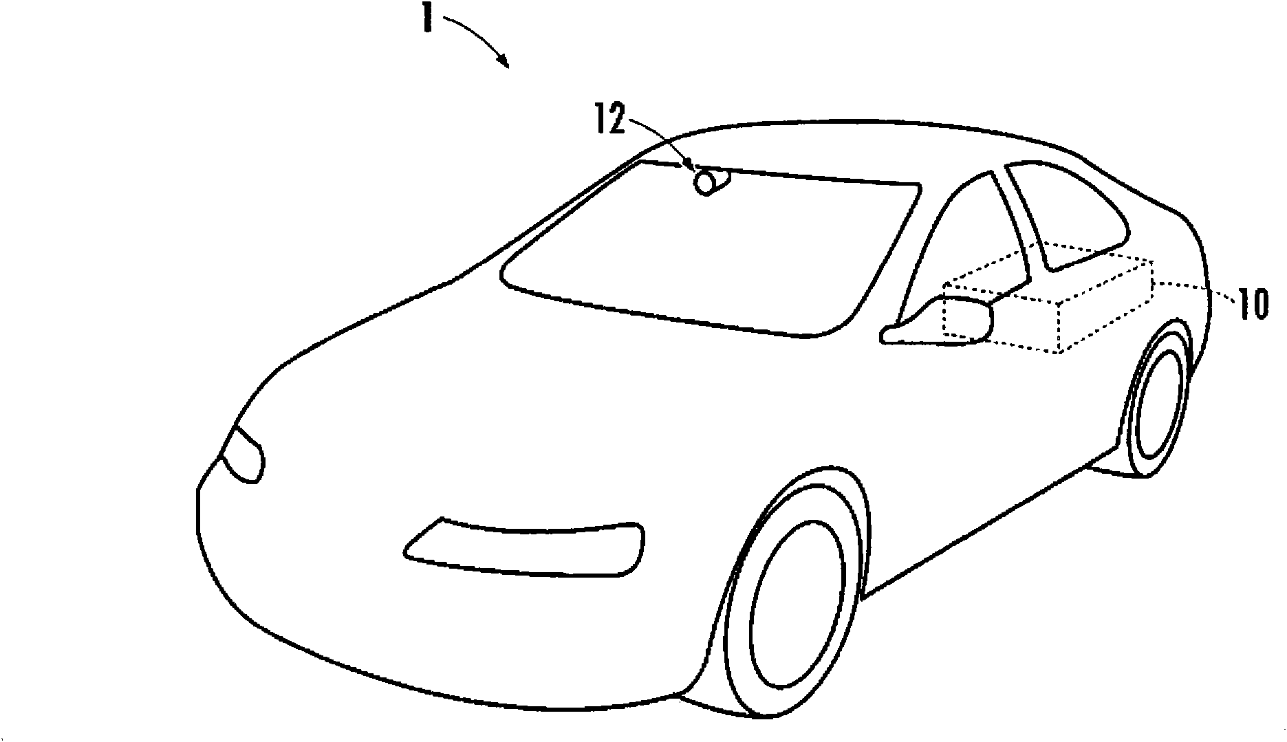
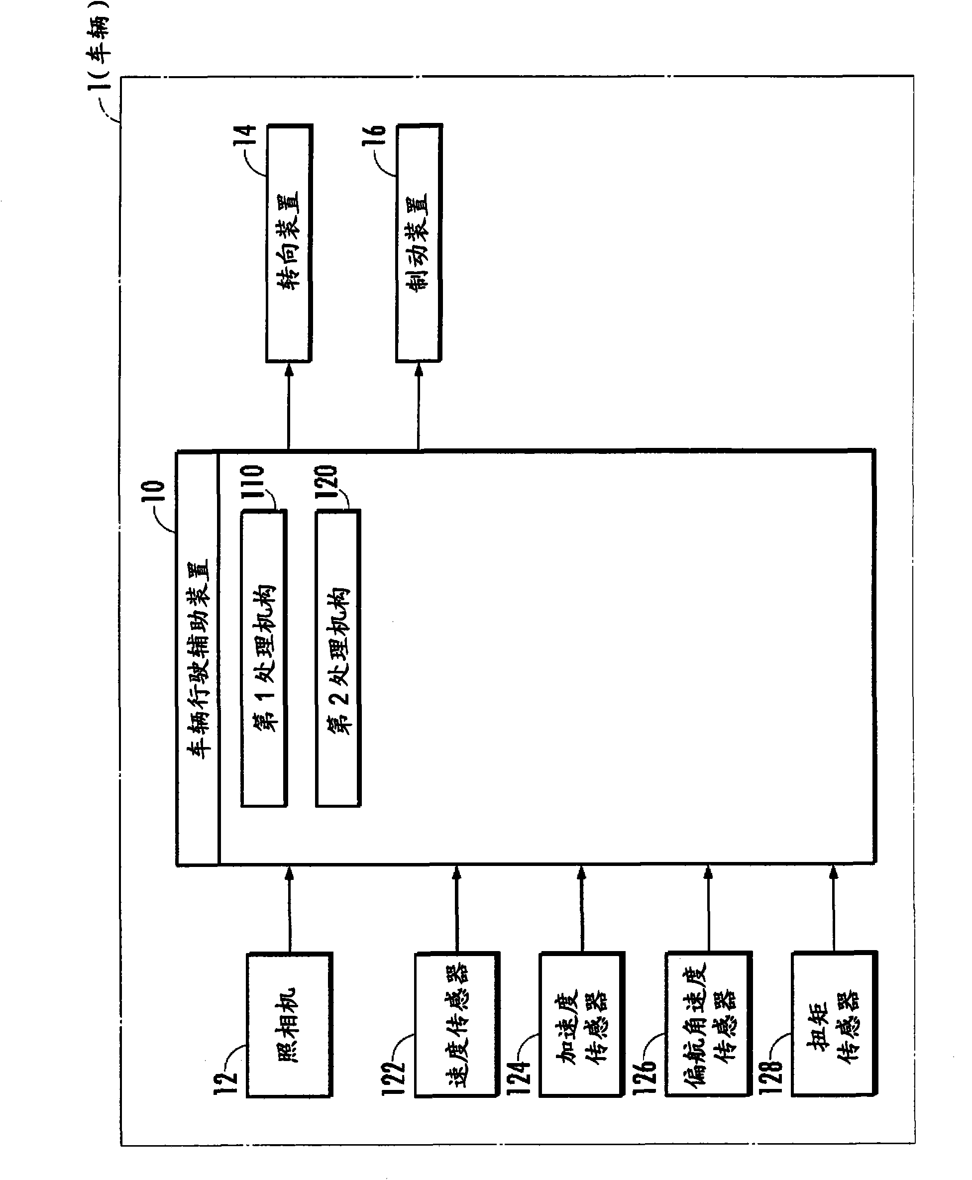
[0027] figure 1 and figure 2The illustrated vehicle (four-wheeled vehicle) 1 is equipped with a CCD camera, a camera (imaging device) 12 such as a CMOS image sensor or a near-infrared camera, and a vehicle driving assistance device 10 . The camera 12 is installed in the interior space of the vehicle compartment, and takes pictures of the scene ahead of the vehicle 1 through the front glass. Such as figure 2 As shown, the vehicle 1 is further equipped with sensors such as a vehicle speed sensor 122 , an acceleration sensor 124 , a yaw rate sensor 126 , and a torque sensor, a steering device 14 , and a braking device 16 . The vehicle speed sensor 122 , the acceleration sensor 124 , and the yaw rate sensor 126 output signals corresponding to the speed, acceleration, and yaw rate of the vehicle 1 , respectively. ...


PUM


Abstract

Provided are a device capable of properly controlling the operation of a steering gear or the like from the viewpoint of support to the stable traveling of a vehicle even in an inappropriate situation for the demarcation of both right and left sides of a travel area by right and left lane marks, and the like. In a vehicle travel support device (10), a virtual travel area can be set as a travel area when a first condition is satisfied, that is, when the space between the right and left lane marks in a road width direction increases to an inappropriate extent from the viewpoint of demarcation of the travel area because the space therebetween gradually increases as the distance from the vehicle increases. The operation of a steering gear (14) or the like is so controlled that the vehicle does not get out of the virtual travel area set as the travel area.

Description

technical field [0001] The invention relates to a device for assisting the running of a vehicle, which assists in controlling the running of the vehicle based on images captured by an imaging device equipped on the vehicle. Background technique [0002] Such a technology exists in the prior art: a camera is equipped on the vehicle, and the driving route marks such as traffic lanes and spikes on the driving road of the vehicle are recognized according to the images taken by the camera (referring to Japanese Invention Patent Laid-Open Gazette 2001-023094). In addition, there is also a technique of identifying lane markers respectively arranged on the left and right sides of the vehicle's driving lane, and controlling the operation of the driving steering device, etc., so that the vehicle does not drive out of the identified left lane markings. The driving area between the side and right lane signs (refer to Japanese Invention Patent Laid-Open Publication No. 2006-264405). ...

Claims


Application Information

Patent Timeline
IPC IPC(8): B60W30/12B62D103/00B62D101/00B60T8/17B60W10/00B62D137/00B60W30/00B60R21/00B62D6/00B62D119/00B60W10/184B60W10/18B60W10/20G08G1/16
CPCB60W2050/146G08G1/167B60W2520/10B60T2201/083B60W10/18B60W10/20B60T8/17557B60W50/08B60T2201/087B62D15/025B60W30/18172G08G1/16B60W2540/18
Inventor 小林幸男
Owner HONDA MOTOR CO LTD
Why Eureka
Try Eureka