Variable compression ratio engine

An engine, internal combustion engine technology, applied in the direction of machines/engines, mechanical equipment, etc., can solve problems such as random changes, and achieve the effect of enhancing rigor, improving flexibility, and durable structure

Inactive Publication Date: 2011-02-09
阿默德 塞伊德 +1
View PDF12 Cites 2 Cited by
  • Summary
  • Abstract
  • Description
  • Claims
  • Application Information

AI Technical Summary

Problems solved by technology

In the above design, the degree of boost cannot be varied arbitrarily with the cam actuation system, and the hydraulically actuated piston suffers from the problems outlined in '537

Method used


Image

  • Variable compression ratio engine
  • Variable compression ratio engine
  • Variable compression ratio engine

Examples


Embodiment Construction

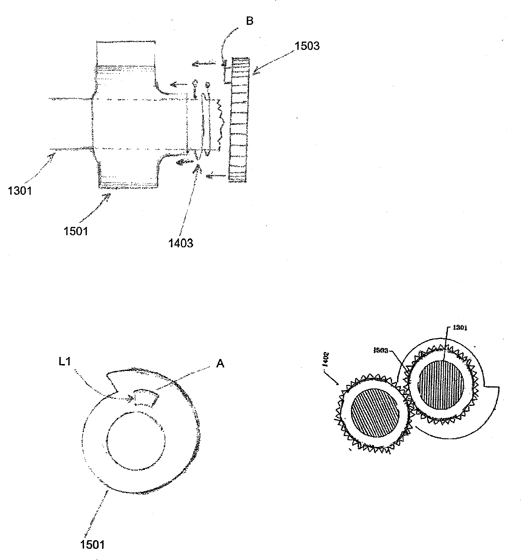
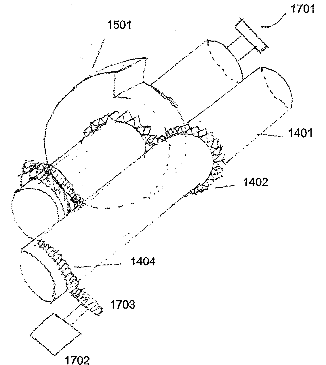
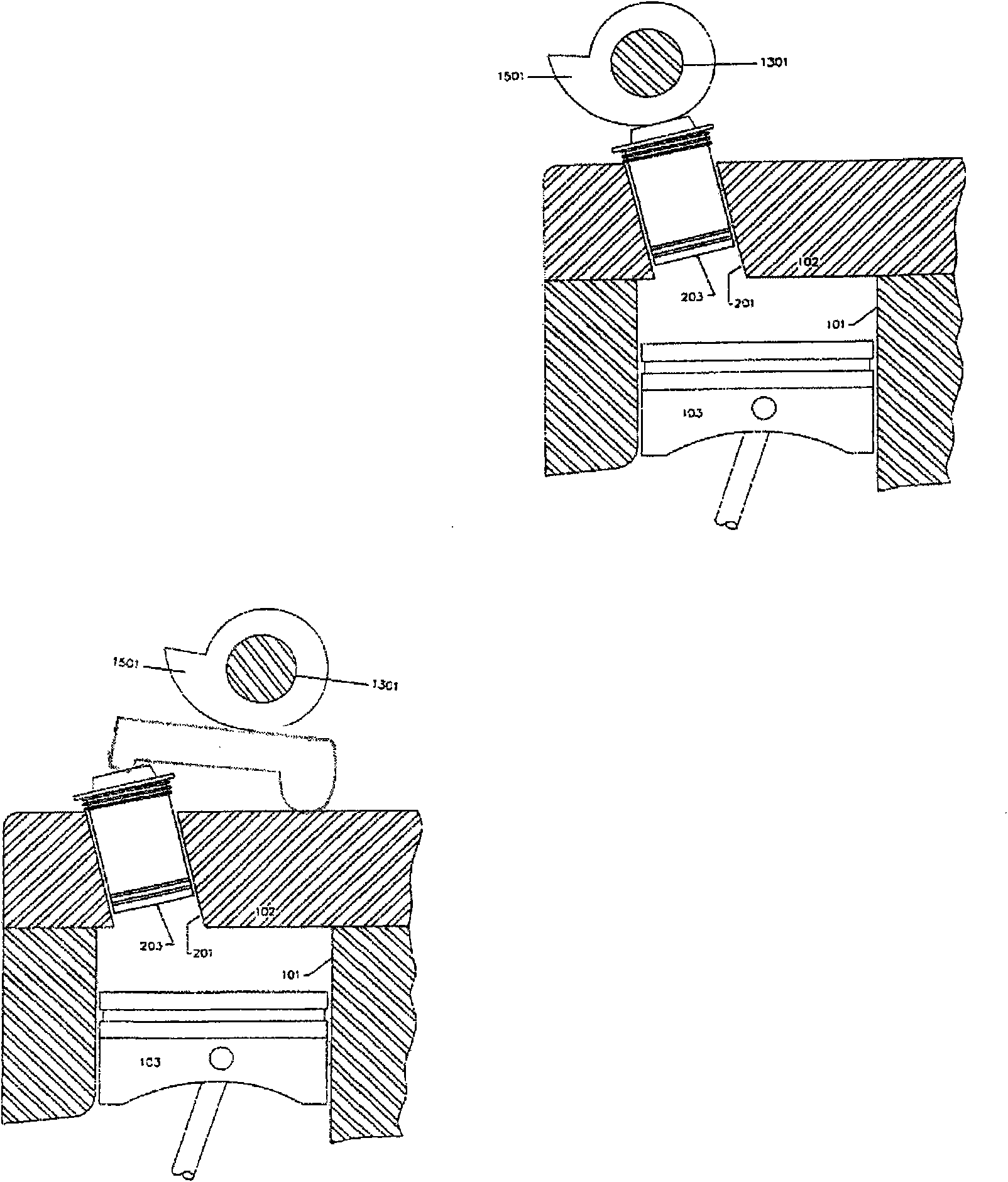
[0027] Referring now to the accompanying drawings, the figure 1 Middle is a cross-sectional view illustrating a cylinder in an internal combustion engine generally indicated at 10 . The engine has a master cylinder 101 , a cylinder head 102 and a master piston 103 . The slave cylinder 201 is formed in the cylinder head 102 and is positioned such that the opening of the slave cylinder 201 communicates with a selected portion of the volume including the interstitial volume at TDC. A sub piston 203 is installed in the sub cylinder 201 . The space below the piston 203 is added to the clearance volume during the calculation of the compression ratio. As the secondary piston descends along the cylinder 201, the clearance volume is reduced and the compression ratio is increased. The opening of the auxiliary cylinder can be made as a narroworifice.

[0028] exist figure 1 In the embodiment shown, the spark plug can be mounted in the secondary piston or elsewhere according to prefe...


PUM


Abstract

A variable compression ratio mechanism for continuously varying the compression ratio of an internal combustion engine while minimizing the power requirement and providing internal clamping to isolate the setting mechanism from the reaction to combustion loads. The mechanism includes a setting cam (1501) actuated via an innovative torque storage system acting on an auxiliary piston (203) in the combustion chamber crown. The mechanism provides very fast and precise transient response without the use of hydraulic control. The invention desirably simplifies the control system and provides an elegant and compact solution for this purpose.

Description

technical field [0001] The invention relates to the field of internal combustion engines, in particular to engines with variable compression ratios. Background technique [0002] Stringent emissions standards coupled with the need to improve fuel economy have forced significant changes in the way motor vehicle powertrains are designed. The main disadvantage of ICE is caused by fixed design features. Key to the breakthrough improvement in ICE performance is the successful implementation of an adaptive engine geometry that enables dynamic optimization of key engine parameters across the entire load / speed range. Currently, design constraints are determined by peak power conditions, but most of the driving occurs at part load engine operation. This allows the possibility to significantly improve overall efficiency and drivability through continuous optimization of design elements. Although the method is applicable to both spark ignition (SI) and diesel (CIDI) engines without ...

Claims


Application Information

Patent Timeline
Patent Type & Authority Applications(China)
IPC IPC(8): F02B75/04
CPCF02B75/042
Inventor 阿默德·塞伊德阿德勒·达
Owner 阿默德 塞伊德
Why Eureka
Try Eureka