
Volumetric quantitative jet valve

An injection valve, volumetric technology, applied in injection devices, lift valves, valve devices, etc., can solve the problems of not meeting the technical requirements of electronic products, difficult to control the amount of glue, difficult to meet the viscosity, etc., to achieve easy use and maintenance. , The effect of shortening the air path and reducing the deviation of the movement position of the striker

Inactive Publication Date: 2013-01-23
陈时雄
View PDF4 Cites 0 Cited by
  • Summary
  • Abstract
  • Description
  • Claims
  • Application Information

AI Technical Summary

Problems solved by technology

Since the outlet aperture is much smaller than the inlet diameter of the glue entering the injection cavity, the packaging material is subjected to the internal pressure generated by the high-speed extrusion of the striker, so that most of the packaging material flows back from the inlet, making it difficult to control the amount of glue injected.
The greater the viscosity, the less accurate the amount of glue
Therefore, the existing technology is difficult to meet the dispensing of high-viscosity packaging materials, and cannot meet the technical requirements of electronic product processing

Method used

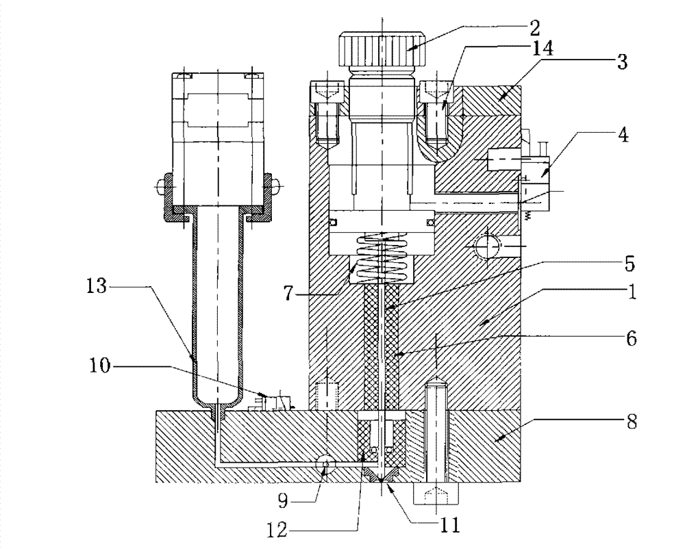

Image

  • Volumetric quantitative jet valve
  • Volumetric quantitative jet valve
  • Volumetric quantitative jet valve

Examples


Embodiment Construction

[0026] The present invention will be described in further detail below in conjunction with the accompanying drawings and embodiments. Such as figure 1 As shown, the volumetric quantitative injection valve of the present invention is composed of a power source assembly and a fluid control box assembly. Four screws are used to pass through the fluid control box, and the fluid control box is fixedly installed on the mounting hole on the power source assembly to form a Volumetric quantitative injection valve.

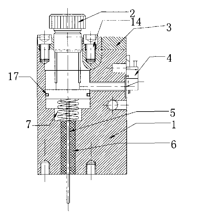
[0027] Such as figure 2 with Figure 4 As shown, the power source assembly is provided with a cylinder A1, and the cylinder A1 has a vertical through hole, and the through hole is gradually reduced from top to bottom and divided into four coaxial holes: the first screw hole 11, the second hole 12, The third hole 13 and the fourth hole 14 . A fifth hole 15 is formed on the side of the cylinder A1. The axis of the fifth hole 15 is perpendicular to the second hole 12 and ...


PUM


Abstract

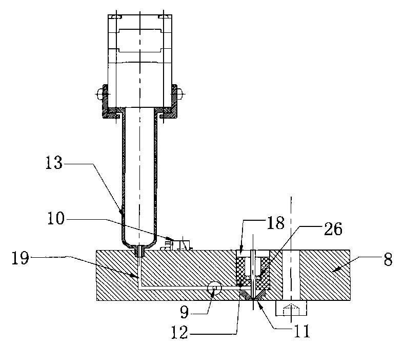
The invention discloses a volumetric quantitative jet valve which aims to solve the technical problems of accurately controlling the jet volume of packaging materials and enabling the jet volume to be adjustable. The volumetric quantitative jet valve of the invention is provided with a jet cavity with an outlet and a striker arranged in the jet cavity, wherein the striker moves to the outlet of the jet cavity when being driven by the power and restores to the original position under the action of the restoring force; the jet cavity is closed and is connected with a hole pipe with a valve; thehole pipe is connected with a charging barrel; and when the striker is driven by the power and moves, the valve is in a closed state. Compared with the prior art, the invention has the characteristics that the valve is arranged between a closed inner cavity in the shape of an inverted cone and a glue inlet hole pipe, so that when the striker downward strikes the glue in the inner cavity of a nozzle, the glue is jetted from the outlet and can not flow back to the glue inlet hole pipe, and the same valve body can be matched with strikers of different diameters to be suitable for different jet volume. The invention is suitable for adhesives, packaging materials, welding glue, paint and lubricating oil for jetting and filling glue and welding components in the electronic industry process.

Description

technical field [0001] The invention relates to a special equipment for the electronic industry, in particular to a spraying device for spraying filling glue, adhesive for welding components, packaging materials, solder glue, paint and lubricating oil. technical background [0002] The size of electronic components used in modern electronic industrial products is getting smaller and more precise, and the installation methods are also diversified. Therefore, it is necessary to deliver the packaging material to the designated position in an extremely precise way without interfering with other components. The environment of use has different physical and chemical performance requirements for packaging materials, such as fluidity, viscosity, and even the performance and flow state of some mixed glues change with time. The existing technology is to inject the encapsulation material to the designated position with the injection valve. First put the packaging material into the bar...

Claims


Application Information

Patent Timeline
Patent Type & Authority Patents(China)
IPC IPC(8): B05C5/00B05C11/10B05B12/00F16K1/00
Inventor 邓楚舒邓穗民
Owner 陈时雄
Learn More