Connecting device of railway vehicle side rolling resistant torsion bar device and vehicle body

An anti-roll torsion bar, railway vehicle technology, applied in the direction of the device for lateral relative movement between the underframe and the bogie, can solve the problems of reduced stiffness, reduced adaptability, reduced bearing capacity, etc., to reduce the vertical stiffness. , Improve the effect of wheel load reduction rate and good compliance coefficient

Inactive Publication Date: 2011-02-16
常州西南交大金路轨道交通科技发展有限公司
View PDF6 Cites 11 Cited by
  • Summary
  • Abstract
  • Description
  • Claims
  • Application Information

AI Technical Summary

Problems solved by technology

In practice, it is found that although the anti-roll torsion bar device significantly improves the compliance coefficient and the lateral comfort of the vehicle when passing through curves, the use of the anti-roll torsion bar device also reduces the adaptability of the vehicle to uneven roads. Reduce the adaptability to changes in line curvature when the vehicle passes through the curve quickly, and cause some important curve passing safety indicators such as wheel load reduction rate and derailment coefficient to be too large, even exceeding the limit requirements in the r

Method used


Image

  • Connecting device of railway vehicle side rolling resistant torsion bar device and vehicle body
  • Connecting device of railway vehicle side rolling resistant torsion bar device and vehicle body
  • Connecting device of railway vehicle side rolling resistant torsion bar device and vehicle body

Examples


Embodiment Construction

[0015] The present invention is described in further detail now in conjunction with accompanying drawing. These drawings are all simplified schematic diagrams, which only illustrate the basic structure of the present invention in a schematic manner, so they only show the configurations related to the present invention.

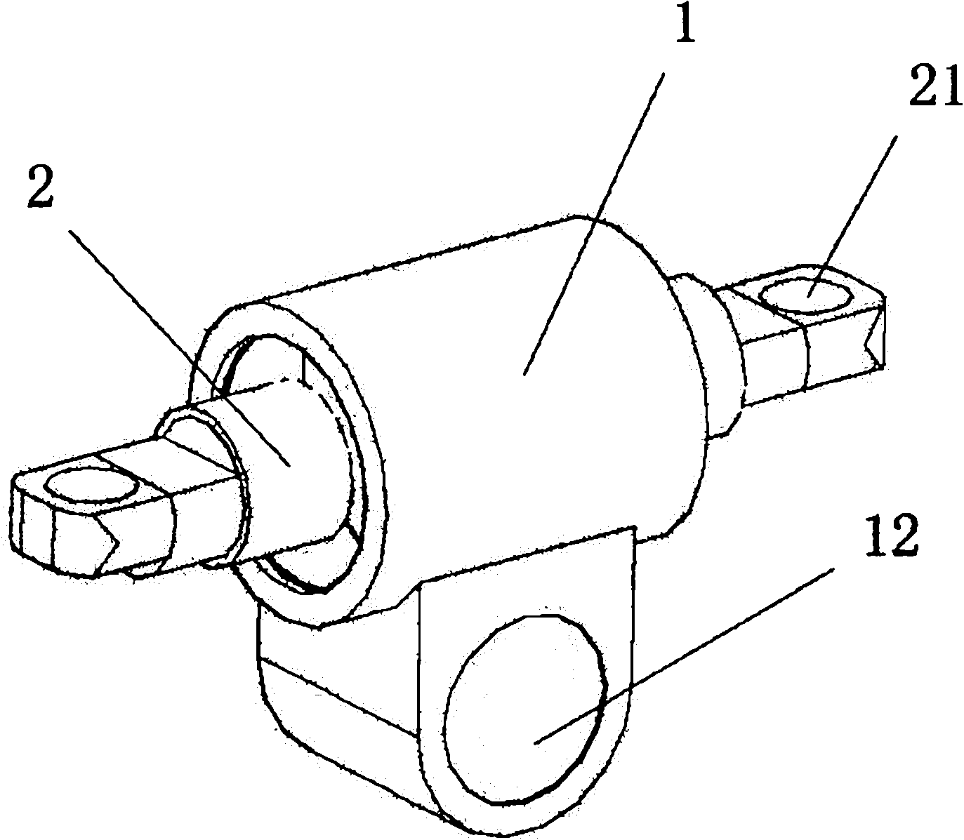
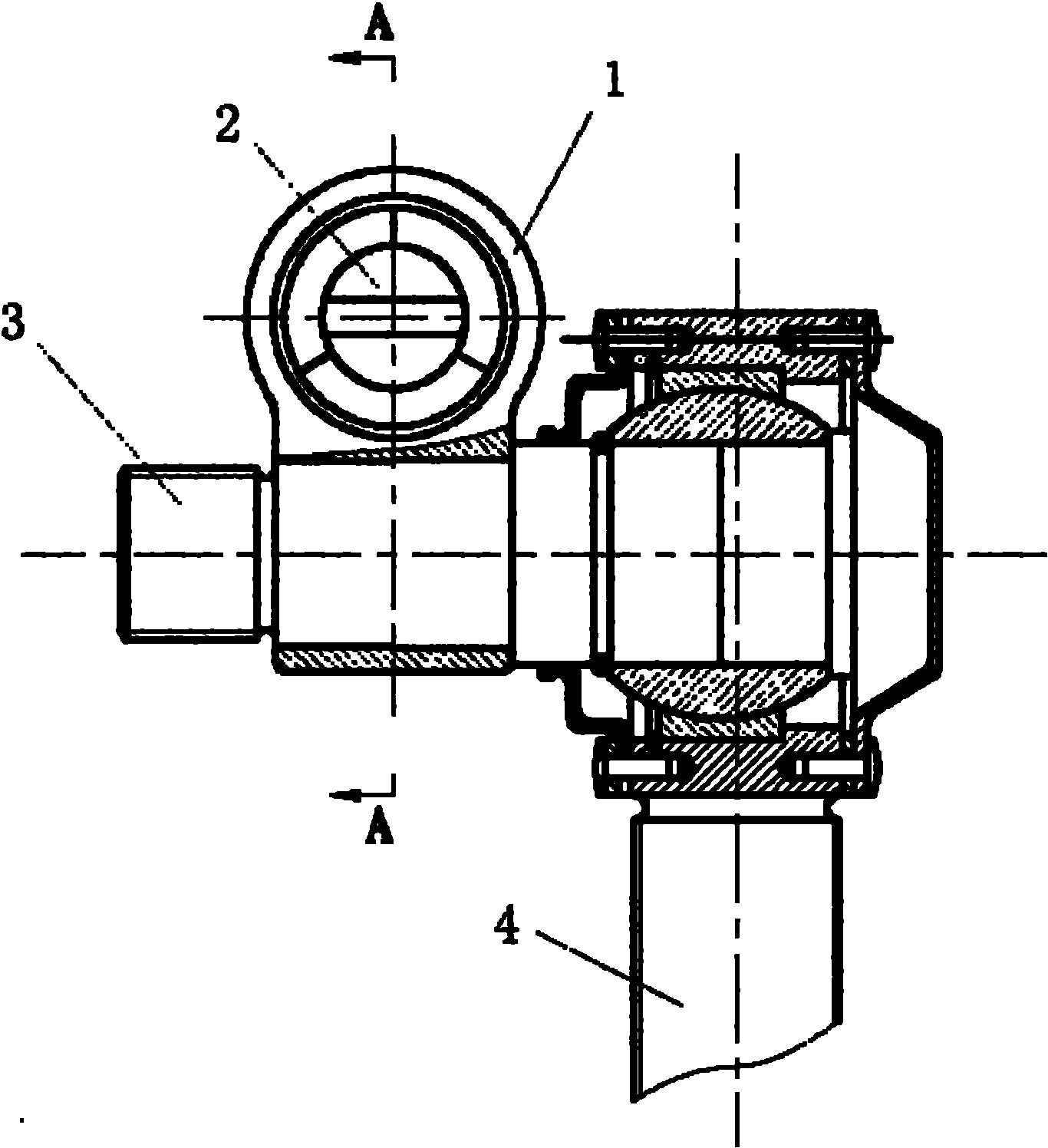
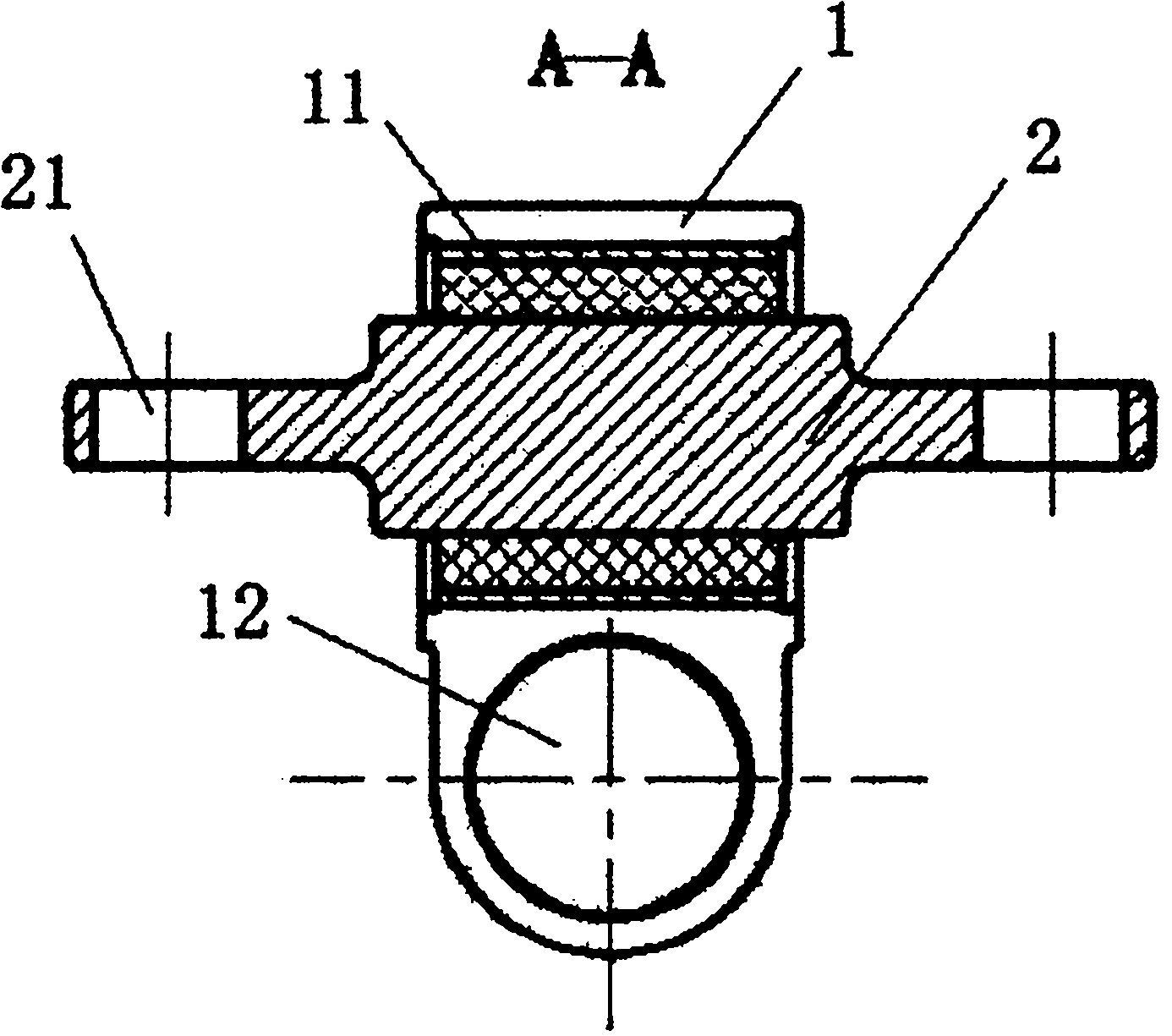
[0016] Such as figure 1 , figure 2 , image 3 The connection device between the anti-rolling torsion bar device and the car body of a railway vehicle in the best embodiment shown includes a structural member 1 for fixed connection with the upper link head shaft 3 of the anti-rolling torsion bar device, For the elastic rubber joint 2 fixedly connected with the vehicle body, the elastic rubber joint 2 is fixed on the structural member 1 perpendicular to the axis of the upper link head shaft 3 connected with the structural member 1 . Structural member 1 is provided with an upper mounting hole 11 and a lower mounting hole 12 that pass through horizontally. The...


PUM


Abstract

The invention relates to the technical field of railway vehicle connecting pieces, in particular to a connecting device of a railway vehicle side rolling resistant torsion bar device and a vehicle body. The connecting device comprises a structure member and an elastic rubber joint, wherein the structure member is used for being fixedly connected with an upper connecting rod head shaft of the side rolling resistant torsion bar device; the elastic rubber joint is used for being fixedly connected with the vehicle body; two installation holes are arranged on the structure member and distributed in the vertical direction; central axes of the holes are vertical to each other; the upper connecting rod head shaft of the side rolling resistant torsion bar device is in interference fit with the lower installation hole; the elastic rubber joint is tightly installed on the upper installation hole and connected with the vehicle body by screws or bolts; and the invention ensures that the vehicle has favorable flexibility coefficient and side rolling resistant capability, can ensure that the side rolling resistant device can not form excessive restraint on the side rolling of the vehicle body relative to a bogie and mitigate moving action force between the vehicle body and the side rolling resistant torsion bar device when the side rolling resistant torsion bar device acts and improves dynamic performance indexes, such as wheel load reducing rate, and the like when the vehicle passes through a curve or is driven on a line with larger line unevenness.

Description

technical field [0001] The invention relates to the technical field of railway vehicle connectors, in particular to a connection device between a railway vehicle anti-rolling torsion bar device and a vehicle body. Background technique [0002] The car bodies of current high-speed passenger cars, main line passenger cars and subway vehicles are all supported on the bogie frame by air springs to obtain better lateral and vertical performance, and the height of empty and heavy vehicles can be adjusted. However, the roll stiffness of the car body relative to the bogie frame is also reduced, so that the vehicle's flexibility coefficient and the roll angle of the car body relative to the bogie when passing a curve are significantly increased, which not only affects the stability and comfort of the vehicle running, but also When the vehicle passes through the curve quickly, the vehicle body is easy to tilt to the outside of the curve under the action of centrifugal force, which red...

Claims


Application Information

Patent Timeline
IPC IPC(8): B61F5/24
Inventor 罗世辉马卫华梁鑫
Owner 常州西南交大金路轨道交通科技发展有限公司
Why Eureka
Try Eureka