Method for measuring surface flatness of light wave array surface or optical reflective surface

A technology of optical reflection and flatness, applied in the field of optical detection, can solve the problems that the parameters of each unit cannot be completely consistent, the light wave array surface is not practical, and the processing is not easy.

Inactive Publication Date: 2011-02-16
西安昂科光电有限公司
View PDF2 Cites 6 Cited by
  • Summary
  • Abstract
  • Description
  • Claims
  • Application Information

AI Technical Summary

Problems solved by technology

[0003] For the interference method, although it has strong intuitiveness and high precision, the test area is often limited, and it is not practical to test a surface with a large area or a light wave array surface
[0004] For the Hartmann and Hartmann Shack methods, a small aperture stop and a lens array are used respectively. The manufacturing precision of the aperture stop and the lens array is very high, the processing is not easy, and the parameters of each unit cannot be fully realized. consistent, so a corresponding error will be introduced

Method used


Image

  • Method for measuring surface flatness of light wave array surface or optical reflective surface
  • Method for measuring surface flatness of light wave array surface or optical reflective surface
  • Method for measuring surface flatness of light wave array surface or optical reflective surface

Examples


Embodiment Construction

[0023] The content of the present invention is described in detail below in conjunction with accompanying drawing:

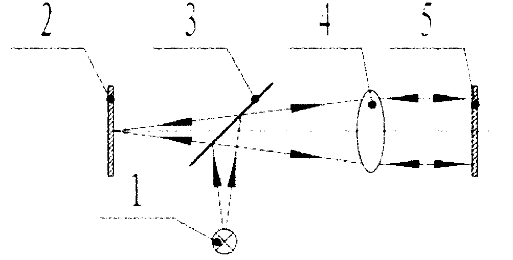
[0024] figure 1 is the structure diagram of the light pipe. The optical target beam is generated by the target generator 1 , and the beam is emitted out of the light pipe through the beam splitter 3 and the lens group 4 , and the beam is reflected by the reflector 5 and then received by the detector 2 . If the mirror deflects, the beam angle will also deflect, and the position of the beam projected on the detector will change and be received and recorded, so as to calculate the deflection angle of the mirror.

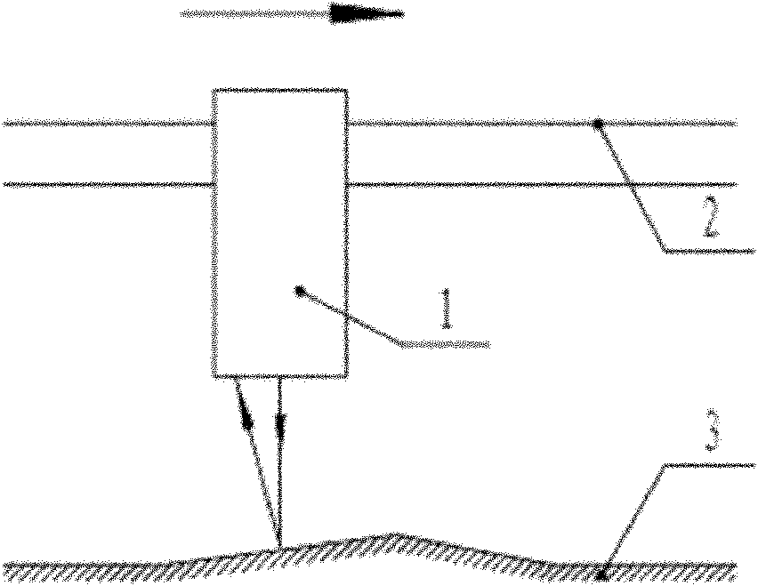
[0025] Use the light pipe directly to scan, then if figure 2 shown. If the area to be measured is an optical reflective surface, the inclination of the reflective surface in the area is calculated by receiving the reflected beam of the light beam emitted by the light pipe detector, and the surface flatness of the entire optical reflective surface is m...


PUM


Abstract

The invention discloses a method for measuring the surface flatness of a light wave array surface or an optical reflective surface, comprising the following steps: (1) directly irradiating a light beam emitted from a light pipe to an area to be detected, or refracting the light beam by a dioptric element to the area to be detected, wherein the area to be detected is an optical reflective surface or a light wave array surface; (2) if the area to be detected is the optical reflective surface, going to step (3); if the area to be detected is the light wave array surface, going to step (4); (3) receiving the light beam irradiated to the optical reflective surface to be detected and reflected by the optical reflective surface via a detector in the light pipe, according to the received reflected light beam, testing the deflection angle of each light beam and the gradient of the optical reflective surface to be detected corresponding to each light beam by the detector, and obtaining the surface flatness of the optical reflective surface; and (4) directly receiving the light wave of the light beam irradiated to the optical reflective surface to be detected by the detector; and if the light wave array surface received by the light pipe deflects, measuring the deflection value thereof. The method of the invention is not limited by test area and is especially good at measuring the surface flatness of the optical reflective surface with large area or the light wave array surface with large calibre.

Description

Technical field: [0001] The invention belongs to the field of optical detection, and relates to an optical plane detection method, in particular to a method for measuring the surface flatness of a light wave array surface or an optical reflection surface. Background technique: [0002] At present, the methods for surface detection of light wave arrays mainly include interferometry, Hartmann sensor measurement, and Hartmann Shack sensor measurement; the detection of surface flatness of optical reflective surfaces mostly uses the method of interference. [0003] For the interferometric method, although it has strong intuitiveness and high precision, the test area is often limited, and it is not practical to test a surface with a large area or a light wave array surface. [0004] For the Hartmann and Hartmann Shack methods, a small aperture stop and a lens array are used respectively. The manufacturing precision of the aperture stop and the lens array is very high, the processi...

Claims


Application Information

Patent Timeline
IPC IPC(8): G01B11/30
Inventor 高文黄育争姚俊
Owner 西安昂科光电有限公司
Why Eureka
Try Eureka