
Flue gas sampling equipment

A technology of flue gas sampling and equipment, applied in the direction of sampling devices, etc., can solve the problems of no purging effect, unresolved filter element clogging, etc., and achieve good results

Inactive Publication Date: 2011-02-16
上海北分科技股份有限公司
View PDF5 Cites 0 Cited by
  • Summary
  • Abstract
  • Description
  • Claims
  • Application Information

AI Technical Summary

Problems solved by technology

[0006] from Figure 12 It can also be seen in the figure that the upper part of the filter element has a purging effect, and the lower part of the filter element (that is, the part facing away from it, the part of the small square hatching in the figure) basically has no purging effect; thus the blockage of the lower part of the filter element has not been solved.

Method used


Image

  • Flue gas sampling equipment
  • Flue gas sampling equipment
  • Flue gas sampling equipment

Examples


Embodiment 1

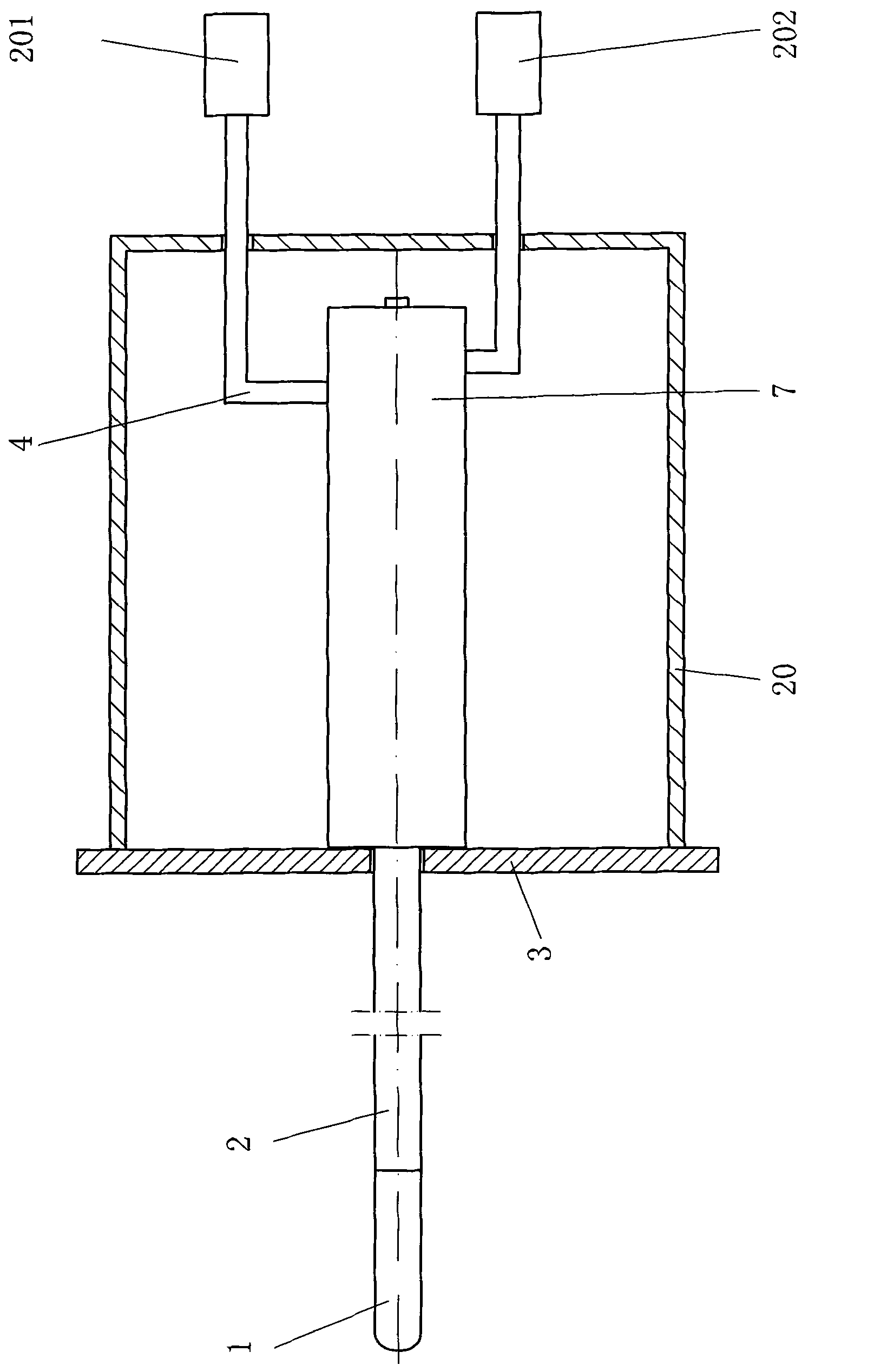
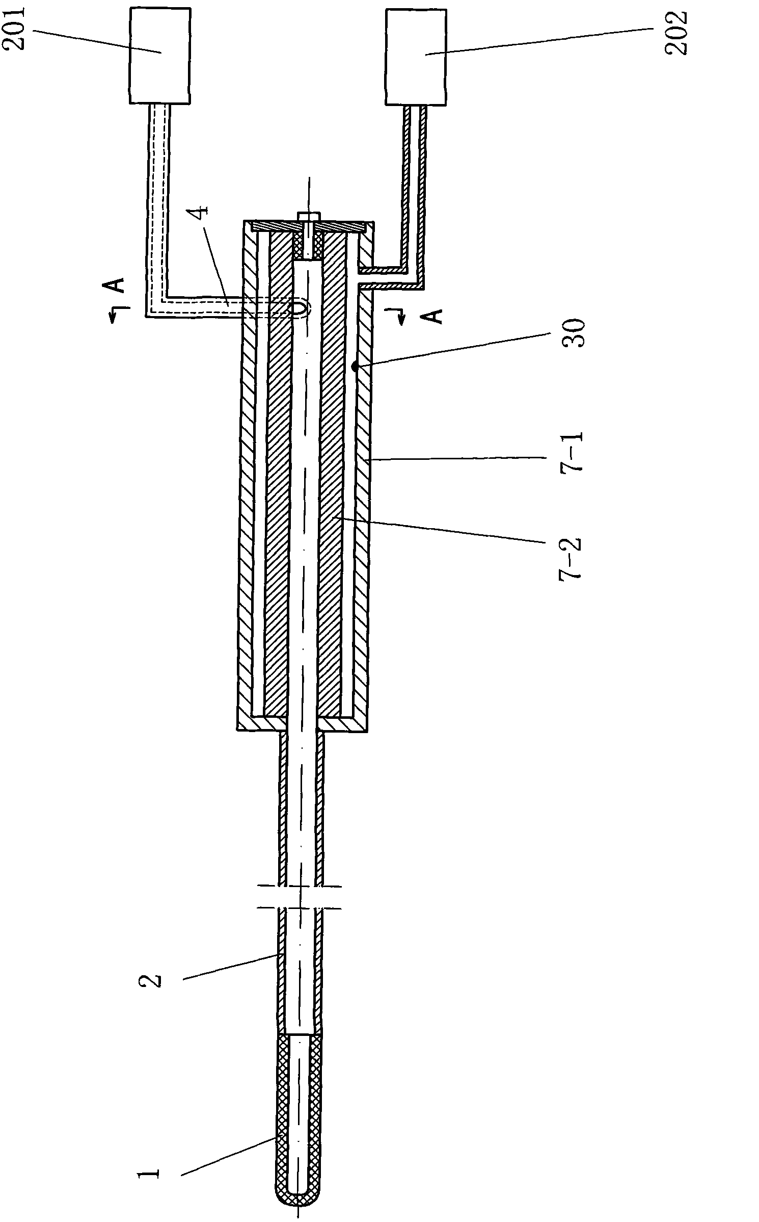
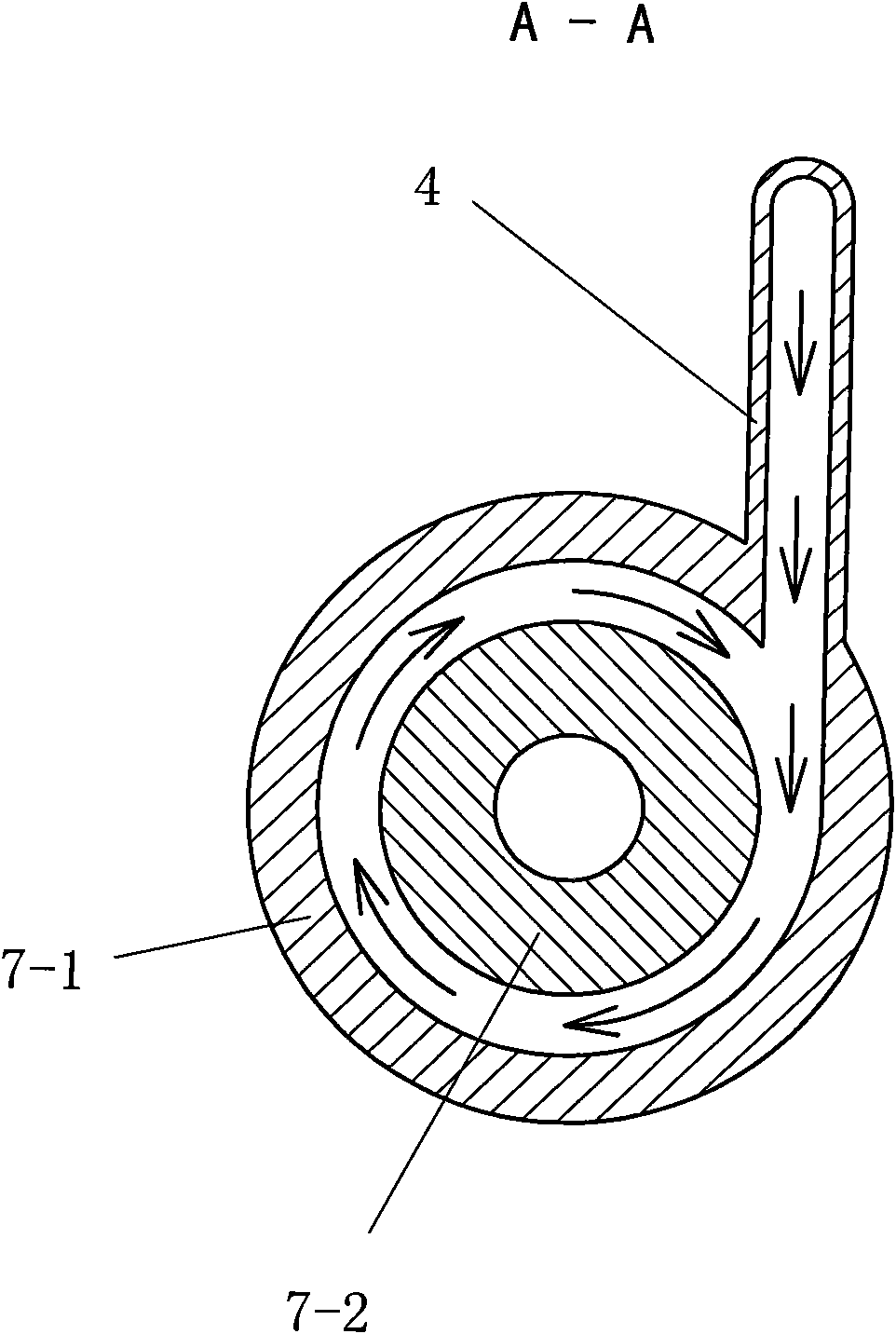
[0067] according to Figure 1 to Figure 11 Expressed content, making flue gas sampling equipment.

[0068] Drawing description: figure 1 is one of the schematic diagrams of the device of the present invention; figure 2 is the second schematic diagram of the device of the present invention; image 3 yes figure 2 A-A sectional view in , and enlarged, the magnification ratio is 3:1; Figure 4 It is a schematic diagram of the filter element in the built-in filter; Figure 5 yes Figure 4 left view of Image 6 It is a schematic diagram of the connection between the built-in filter housing and the blowback air pipe; Figure 7 yes Image 6 left view of Figure 8 yes Image 6 top view of Figure 9 yes Image 6 right view of Figure 10 yes Figure 8 C-C sectional view of ; Figure 11 yes Image 6 B-B direction sectional view. 1. Pre-filter; 2. Probing rod; 3. Mounting plate; 4. Blowback air pipe; 7. Built-in filter; 7-1. Outer cover; 7-2. Shell; 30. Probe; 201. Air...


PUM


Abstract

The invention relates to the technical field of flue gas detection and analysis, and discloses flue gas sampling equipment. In order to solve the problem that blockage cannot be completely removed in the prior art, the technical scheme is provided. The equipment is characterized in that: a built-in filter (7) comprises a filter element (7-2) and an outer cover (7-1); the filter element (7-2) is a transverse cylinder; the outer cover (7-1) is a transverse barrel; the filter element (7-2) is positioned in the outer cover (7-1) and is coaxial with the outer cover (7-1); a circular tube-shaped gap exists between the outer surface circular wall of the filter element (7-2) and the inner side circular wall of a barrel body of the outer cover (7-1); the two ends of the filter element (7-2) are hermetically connected with or adjacent to the barrel body and a barrel cover respectively; and one end of a gas backblowing pipe (4) is communicated with a gas control part (201), while the other end is communicated with the barrel body of the outer cover (7-1) at a gas backblowing hole through a tangent structure. The flue gas sampling equipment has the advantages that: backblowing airflow is rotary or spiral, so the blockage on the filter element can be completely removed and dead angles which cannot be removed do not exist any more.

Description

technical field [0001] The invention relates to the technical field of smoke detection and analysis, in particular to a smoke sampling device. Background technique [0002] In the prior art, a flue gas analysis instrument is composed of multiple devices (or mechanisms) to achieve various functions such as sampling and detection. [0003] Since the untreated flue gas to be tested often contains flue gas dust, impurities, particles, etc., it is usually necessary to use a filter element for filtration during the sampling stage. The result of filtration is: on the one hand, the flue gas dust, impurities, particles, etc. are blocked; on the other hand, a lot of flue gas dust, impurities, particles, etc. are deposited on the surface of the filter element, which causes the surface of the filter element to be blocked. [0004] In order to solve the problem of blockage on the surface of the filter element, the technical measure adopted in the flue gas analysis instrument is to set u...

Claims


Application Information

Patent Timeline
IPC IPC(8): G01N1/10
Inventor 廖明君徐颖何盼乔正辉
Owner 上海北分科技股份有限公司
Features
  • Generate Ideas
  • Intellectual Property
  • Life Sciences
  • Materials
  • Tech Scout
  • Unparalleled Data Quality
  • Higher Quality Content
  • 60% Fewer Hallucinations
Learn More