
Rotary piston internal combustion engine power unit

A power unit, rotary technology, applied in the field of rotary piston internal combustion engine power units

Inactive Publication Date: 2011-02-16
戴维·W.·加赛德
View PDF5 Cites 2 Cited by
  • Summary
  • Abstract
  • Description
  • Claims
  • Application Information

AI Technical Summary

Problems solved by technology

However, other sfc, HC emission, and emission noise characteristics have not yet been attractive enough for electric vehicle manufacturers to incorporate such engines into product designs

Method used


Image

  • Rotary piston internal combustion engine power unit
  • Rotary piston internal combustion engine power unit
  • Rotary piston internal combustion engine power unit

Examples


Embodiment Construction

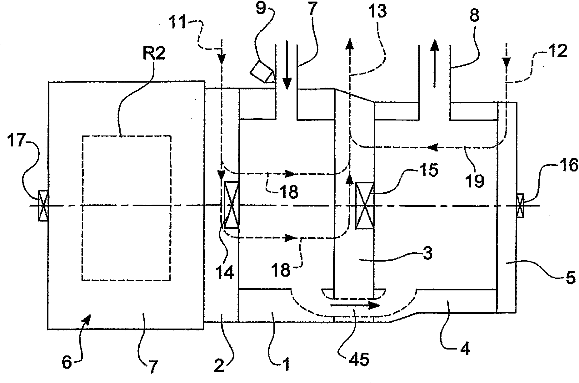
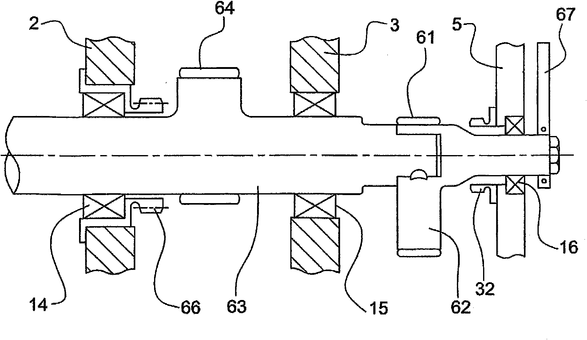
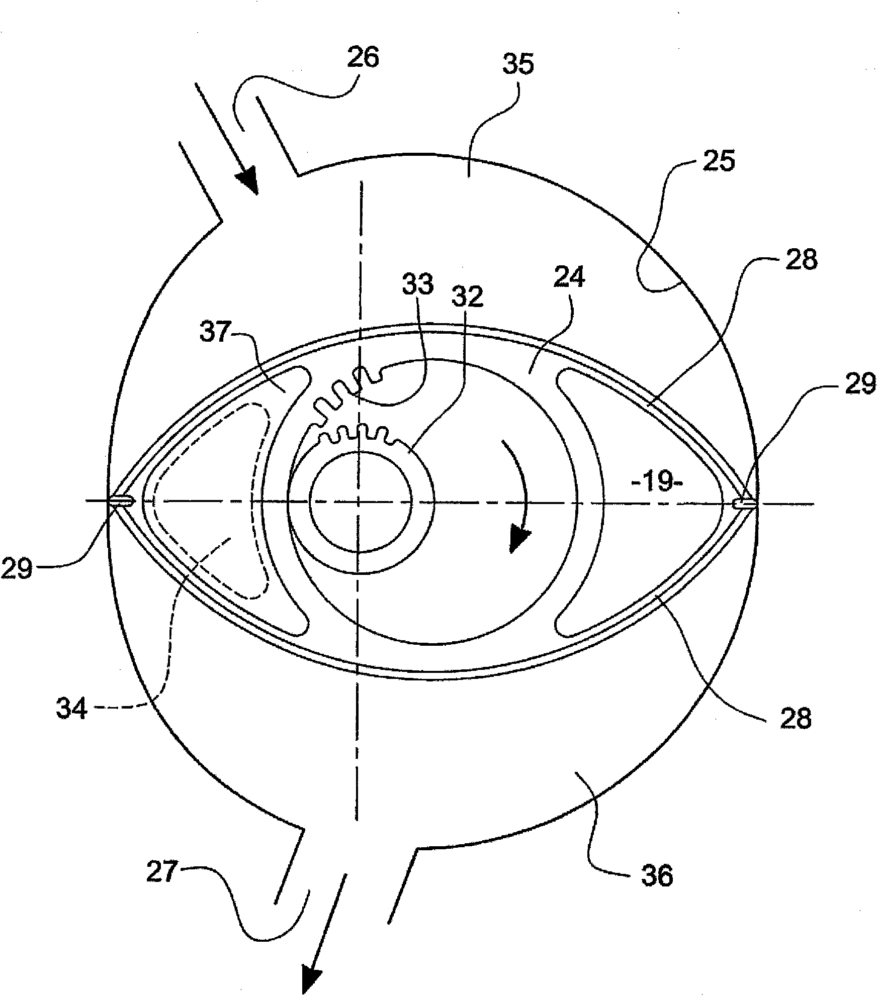
[0035] refer to figure 1 with 2 , the engine unit includes a rotor housing 1, end sleeves 2 and 3, and an introduction pipe 7. The expander unit is mounted coaxially with the engine unit and projects outwardly from the engine unit through a shared composite end sleeve 3 . The expander unit includes a rotor housing 4 , an outer end sleeve 5 and a discharge pipe 8 . The rotor 24 of the expander unit (see image 3 ) meshes with the stationary gear 32 and is mounted on an extension 62 of the motor eccentric shaft 63 which is journalled in two main bearings 14, 15 mounted in the end sleeves 2, 3 respectively. The small tail bearing 16 of the expander unit is depicted adjacent to the external counterweight 67 . The shafts 63, 62 of the engine unit and expander unit are thus connected for common rotation.

[0036] The expander unit rotor 24 rotates at half the speed of the shaft 62 on which the expander unit rotor 24 is mounted.

[0037] For engine unit rotor R (see Figure 8)...


PUM


Abstract

A power unit (14) which has a spark-ignition engine unit (1 ) of the Wankel type including a three flanked rotary piston (R) mounted on an eccentric shaft (63) rotating eccentrically within a cavity within a two lobed epitroochoidal inner peripheral surface (14), the cavity including an inlet port (7) through which air at ambient pressure is induced into the working chambers, and an outlet port (45) through which exhaust gasses are exhausted from the working chambers, and the power unit also including a rotary expander unit (4) which has a two flanked rotor (24) mounted on an eccentric shaft (12) rotating eccentrically within a single lobed epitrochoidal chamber (25), both shafts (62, 63) being coupled to rotate together, and the exhaust port (45) of epitrochoidal cavity of the engine unit (1 ) being connected to an inlet port (26) of the expander unit (4) so that the exhaust gasses from the engine unit (1 ) are further expanded in the expander unit (4).

Description

technical field [0001] The invention relates to a rotary piston internal combustion engine power unit. Background technique [0002] More specifically, the invention relates to a power unit comprising a so-called Wankel engine, in which rotary pistons or so-called rotors are joined by housings or so-called rotor housings with endhousings or so-called end sleeves Rotate in the cavity formed by (end casings), the outer periphery of the rotor (periphery) and the inner peripheral surface of the cavity are shaped so that a working chamber is formed between the rotor and the inner wall, when the rotor rotates, the volume of the chamber changes, and the cavity has an inlet port and discharge port. In the best-known example of a related type of engine, the cavity is provided by a stationary rotor casing having an inner peripheral surface of two lobed epitrochoidal shape, and presents a generally triangular shape but with convex arcuate sides (convex arcuate flanks), the seal at th...

Claims


Application Information

Patent Timeline
IPC IPC(8): F02B53/00F02B41/02
CPCF02B41/02Y02T10/17F02B53/00F02B2053/005Y02T10/12F01C1/22F01C11/004F02B53/14
Inventor 戴维·W.·加赛德
Owner 戴维·W.·加赛德
Learn More