Automatic wire threader of wire electric discharge machining device

A technology of electric discharge machining and automatic line, which is applied in the direction of electric processing equipment, metal processing equipment, electrode manufacturing, etc., can solve the problems of large positioning error, poor precision, and low durability of split molds, and achieve the goal of reducing production costs and improving safety Effect

Active Publication Date: 2011-02-23
SODICK CO LTD
View PDF7 Cites 5 Cited by
  • Summary
  • Abstract
  • Description
  • Claims
  • Application Information

AI Technical Summary

Problems solved by technology

[0013] However, it can be considered that the split mold has low durability and is prone to wear
In addition, it can be considered that the positioning error of the split die is larger than that of the round die
In particular, split dies are considered to be less accurate than round dies in processing using a wire electrode inclined between the upper and lower wire guides, so-called "taper processing".

Method used


Image

  • Automatic wire threader of wire electric discharge machining device
  • Automatic wire threader of wire electric discharge machining device
  • Automatic wire threader of wire electric discharge machining device

Examples


Embodiment Construction

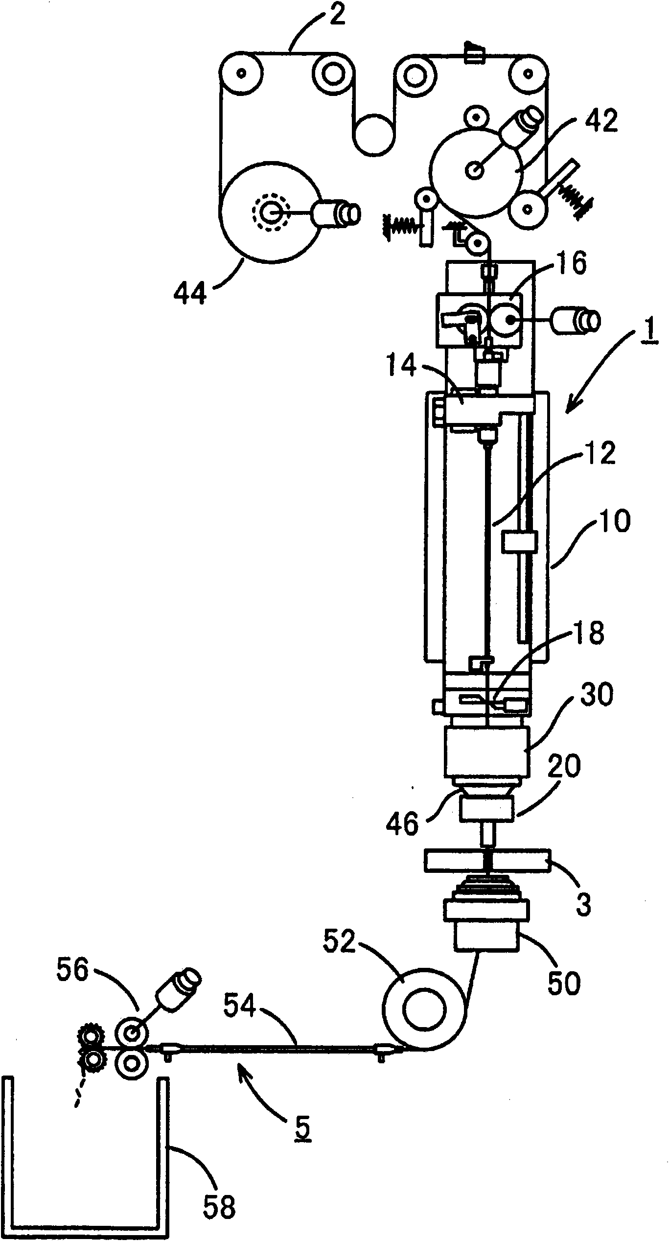
[0050] Refer below Figure 1 to Figure 6 The automatic wire inserting device of the present invention will be described. From figure 1 The automatic line insertion device in the model omits the jet nozzle disassembly device.

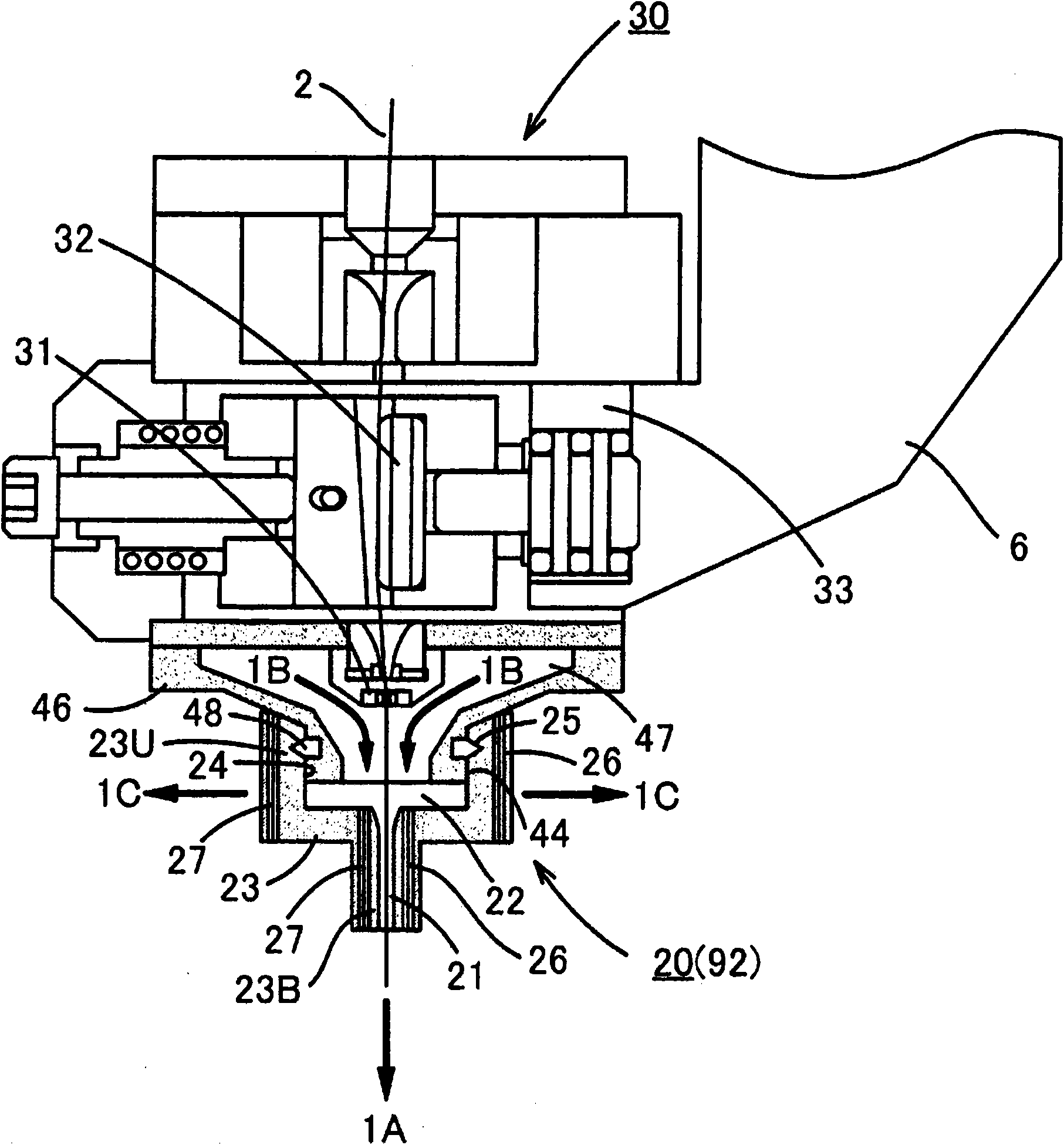
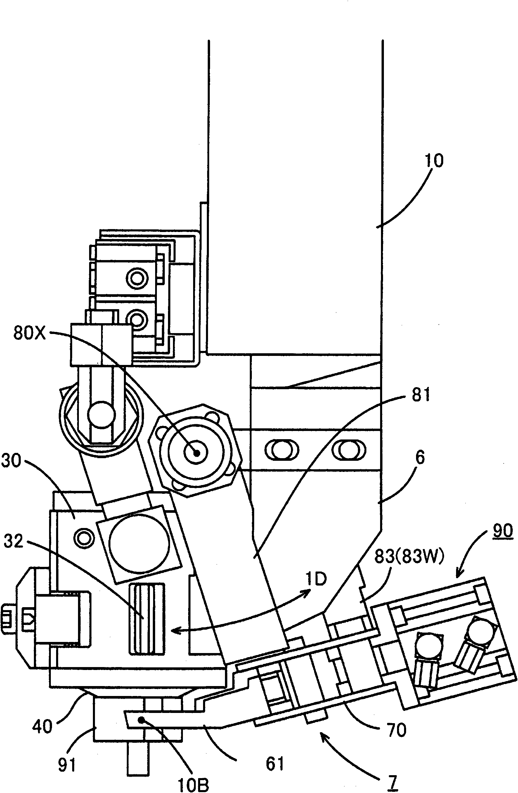
[0051] The main body 10 of the automatic wire insertion device 1 is installed on the processing head which moves up and down. Such as image 3 and Figure 4 As shown in , the jet nozzle demounting device 90 for installing / detaching the jet nozzle 20 relative to the jet nozzle 46 is provided on the main body 10 . An upper guide assembly 30 is fixed to the lower end of the main body 10 . The height of the upper guide assembly 30 can be adjusted by moving the processing head up and down to move the main body 10 up and down.

[0052] The upper guide assembly 30 has at its lower end a jet nozzle 46 that forms a water column coaxially with the feeding direction of the wire electrode 2 . The machining gap formed between the wire electrode 2 and the work...


PUM

PropertyMeasurementUnit
diameteraaaaaaaaaa

Abstract

An automatic wire threader comprises a jet nozzle (20) configured from first and second divided nozzles (91, 92). The jet nozzle (20) is attachable to a jet stream nozzle (46). The automatic wire threader further comprises a first finger (61) for supporting the first divided nozzle (91), a second finger (62) for supporting the second divided nozzle (92), and an opening and closing unit (70) for opening and closing the first and second fingers (61, 62) to unite or separate the first and second divided nozzles (91, 92) and simultaneously couple or detach the jet nozzle (20) to or from the jet stream nozzle (46). An annular groove (25) is formed in the inner peripheral surface (24) of the jet nozzle (20), and an annular protrusion (48) that is fitted into the annular groove (25) is formed on the outer peripheral surface of the jet stream nozzle (46). The first and second divided nozzles (91, 92) comprise divided surfaces (23U, 23B), respectively. A valley-shaped groove is formed in the first divided surface and a mountain-shaped protrusion that is fitted into the valley-shaped groove is formed on the second divided surface.

Description

technical field [0001] The present invention relates to a wire-cut electrical discharge machining device that processes a workpiece by generating discharge in a machining gap formed between a wire electrode that moves between a pair of wire guides and a workpiece. In particular, the present invention relates to an automatic wire insertion device for a wire-cut electrical discharge machining device that automatically bridges a wire electrode between a pair of wire guides. Background technique [0002] The wire-cut electrical discharge processing device with a numerical control device has a so-called automatic wire threading device (Automatic Wire Threader), which automatically makes the wire electrode pass through the upper wire guide, the starting hole, and the lower wire guide in sequence, and is captured by the winding roller. . The start hole is a hole of about 1 mm formed in the workpiece before electric discharge machining. Typically, the wire electrode has a diameter...

Claims


Application Information

Patent Timeline
Patent Type & Authority Applications(China)
IPC IPC(8): B23H7/10
CPCB23H7/102
Inventor 保坂昭夫
Owner SODICK CO LTD
Why Eureka
Try Eureka