Check patentability & draft patents in minutes with Patsnap Eureka AI!

Pipe joint cover

A technology for joints and covers, which is applied in the direction of pipe joints, hose connection devices, pipes/pipe joints/fittings, etc., which can solve problems such as troublesome operation, installation of pipe joint covers, and inability to move pipe joint covers. Achieve improved sealing and easy installation

Inactive Publication Date: 2011-03-02
NIFCO INC
View PDF1 Cites 0 Cited by
  • Summary
  • Abstract
  • Description
  • Claims
  • Application Information

AI Technical Summary

Problems solved by technology

[0006] However, in the above-mentioned conventional pipe joint cover, since the sealing part for sealing the joint part of the high-pressure fuel pipe is provided so as to sandwich the joint part, the pipe joint cover cannot be installed on the high-pressure fuel pipe to avoid the high pressure. At the joint part of the fuel pipe, the pipe joint cover cannot be moved along the high-pressure fuel pipe, and the joint part of the high-pressure fuel pipe cannot be covered by the pipe joint cover.
[0007] Therefore, if a plurality of, for example, four (in the case of four cylinders), or six (in the case of six cylinders), or eight (in the case of eight cylinders) joints of high-pressure fuel pipes are close, it is difficult to install the pipe joint cover. In order to cover each joint, and the operation is troublesome

Method used


Image

  • Pipe joint cover
  • Pipe joint cover
  • Pipe joint cover

Examples


Embodiment Construction

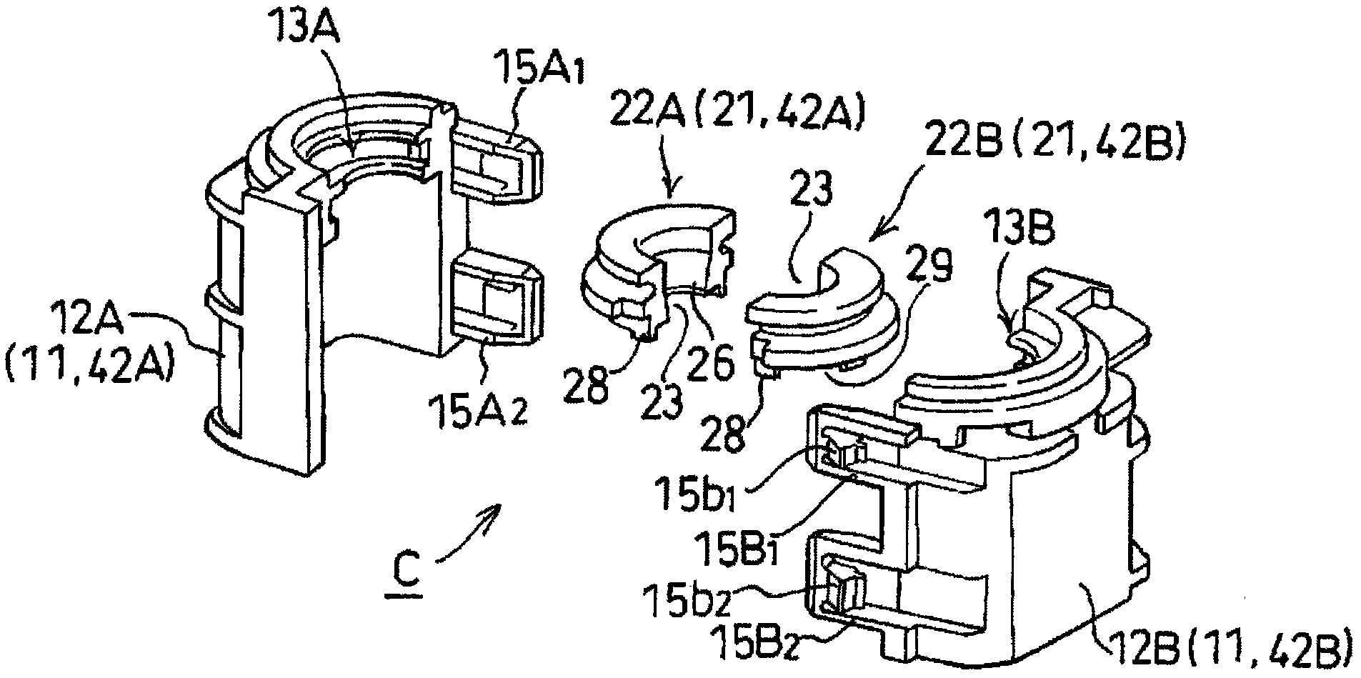
[0052] Hereinafter, embodiments of the present invention will be described based on the drawings.

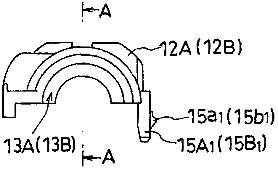
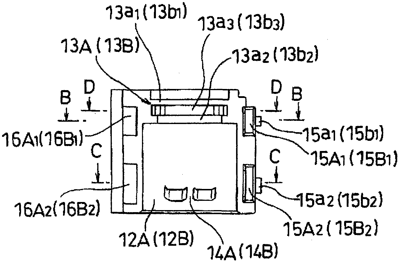
[0053] figure 1 It is an exploded perspective view showing a pipe joint cover as an embodiment of the present invention. figure 2 yes means figure 1 A plan view of the split hood section shown. image 3 yes means figure 2 Front view of split hood section shown. Figure 4 yes means figure 2 Rear view of split hood portion shown. Figure 5 yes means figure 2 Right side view of split hood portion shown. in addition, Figure 6 is along figure 2 Sectional view of line A-A. Figure 7 is along image 3 Sectional view of the B-B line. Figure 8 is along image 3 Sectional view of line C-C. Figure 9 is along image 3 Sectional view of line D-D.

[0054] in addition, Figure 10 yes means figure 1 Plan view of the segmented occlusion shown. Figure 11 yes means Figure 10 Front view of the segmented occlusion shown. Figure 12 yes means Figure 10 Posterior view...


PUM


Abstract

Disclosed is a pipe joint cover (C) that covers a joint (U) of a high-pressure fuel pipe (61) of an engine, wherein one end of a cylindrical cover part (12A, 12B) is blocked by a blocking part (22A, 22B) having a pipe insertion hole (23). The blocking part (22A, 22B) has a seal part (26) where the inner circumference that forms the pipe insertion hole (23) adheres to the outer periphery of the high-pressure fuel pipe (61), and a receiving chamber (31) positioned on the outer side of the seal part (26), the bottom of which opens up to receive fuel that is sprayed from the joint (U). The bottomedge of the outer wall (28) of the reception chamber that forms the reception chamber (31) contacts the upper surface of the mounting nut (71) that constitutes the joint (U). Such a pipe joint cover can be easily installed, and can ensure that sprayed fuel is prevented from being dispersed to the surroundings.

Description

technical field [0001] The present invention relates to a pipe joint cover that covers a joint of a high-pressure fuel pipe so that, for example, fuel injected from the joint of a high-pressure fuel pipe of a diesel engine does not splash around. Background technique [0002] When fuel leaks from the junction of the high-pressure fuel pipe of the diesel engine, the fuel is sprayed in a high-temperature, high-pressure mist from between the high-pressure fuel pipe and the connecting piece (such as a nut) in one direction, which may cause a fire and is very dangerous. [0003] Therefore, there has been proposed a pipe joint cover that prevents fuel leaked from the joint of the high-pressure fuel pipe from splashing around and recovers the fuel leaked from the joint. [0004] The pipe joint cover consists of two protective elements forming a closed chamber in which the fuel leaked from the joint is enclosed, a discharge port provided on one of the two protective elements, and a ...

Claims


Application Information

Patent Timeline
Patent Type & Authority Applications(China)
IPC IPC(8): F02M55/02F02M63/00F16L57/00
CPCF02M2200/18F16L55/179F02M55/02F02M55/005F16L2201/20F02M2200/16F02M55/00F16L19/028F16L35/00
Inventor 西田隆平
Owner NIFCO INC
Features
  • R&D
  • Intellectual Property
  • Life Sciences
  • Materials
  • Tech Scout
  • Unparalleled Data Quality
  • Higher Quality Content
  • 60% Fewer Hallucinations
Learn More