Pneumatic gate valve
A technology of pneumatic rams and rams, applied in the direction of sliding valves, valve details, valve devices, etc., can solve the problems of affecting the sealing performance of ram valves and the inability to remove deposited materials, and achieve the effect of increasing the cleaning range
- Summary
- Abstract
- Description
- Claims
- Application Information
AI Technical Summary
Problems solved by technology
Method used
Image
Examples
Embodiment 1
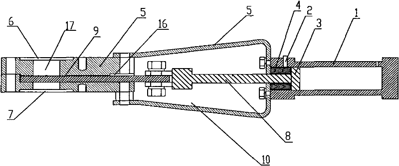
[0038] Such as figure 1 Shown is a structural diagram of the pneumatic gate valve of the present invention. The pneumatic gate valve in this embodiment includes a cylinder 1 and a piston 3 located in the cylinder 1 for resetting the position of the piston 3. A biasing force component 4; a power medium inlet and outlet 2 is provided on the cylinder body 1 below the piston 3, and the power medium inlet and outlet 2 is connected with an external air source;
[0039]A valve body 5 is connected to the cylinder body 1, a valve chamber 10 is provided at one end of the valve body 5 close to the cylinder body 1, and a gate chamber 16 is provided at the other end inside the valve body 5;
[0040] The valve body 5 is provided with a material inlet 6 and a material outlet 7, and the material inlet 6 and the material outlet 7 are communicated to form a blanking cavity 17, and the blanking cavity 17 and the material outlet 7 are connected. The gate cavity 16 is arranged vertically and comm...
Embodiment 2
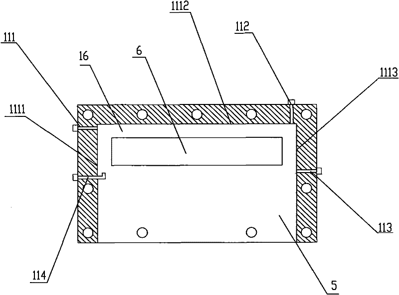
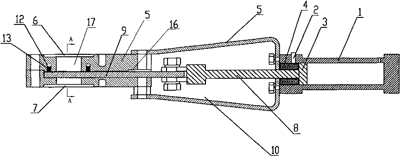
[0051] Such as image 3 Shown is the structural diagram of the pneumatic gate valve provided with the air sealing device according to the present invention. Compared with the pneumatic gate valve described in embodiment 1, the gate cavity 16 is set to be rectangular in this embodiment ;
[0052] The upper side wall of the gate cavity 16 is provided with an air-tight groove 12, and an air-tight device for fixing and limiting the gate 9 is arranged inside the air-tight groove 12, and the air-tight groove 12 is connected with the set The air-tight air inlet 14 on the valve body 5 is connected; the central axis of the third purge air inlet 113 is located in the opening extension area of the air-tight groove 12 close to the opening groove of the valve cavity 10 Inside; the central axis of the first purge air inlet 111 is located in the opening extension area of the air seal groove 12 close to the opening groove in the opposite direction of the valve cavity 10; the air seal dev...
Embodiment 3
[0059] Such as Figure 5 Shown is the structural diagram of the gate valve provided with the scraping device according to the present invention, in this embodiment, on the basis of the structure of the foregoing embodiment 1 or embodiment 2, on one side of the gate valve There is a groove that can be embedded in the scraping device; in this embodiment, the groove is selected to be an annular groove; the scraping device is in contact with the side wall of the shutter 9, and here, the The side wall of the gate 9 refers to the side of the gate valve facing the feed inlet 6 ; the scraping device described in this embodiment is selected as a sealing strip 15 .
[0060] When the pneumatic gate valve described in this embodiment is working, the sealing strip 15 will scrape off the material particles on the gate 9 in the process of sliding relative to the gate 9 to avoid the Material particles enter the valve body 5 along with the shutter 9 .
PUM
 Abstract
Description
Claims
Application Information
 - R&D
- Intellectual Property
- Life Sciences
- Materials
- Tech Scout
- Unparalleled Data Quality
- Higher Quality Content
- 60% Fewer Hallucinations
Browse by: Latest US Patents, China's latest patents, Technical Efficacy Thesaurus, Application Domain, Technology Topic, Popular Technical Reports.
© 2025 PatSnap. All rights reserved.Legal|Privacy policy|Modern Slavery Act Transparency Statement|Sitemap|About US| Contact US: help@patsnap.com


