
Tracking display method and device for screen menu

A technology of screen menu and display method, applied in the input/output process of data processing, instruments, electrical digital data processing and other directions, can solve the problems of small display area, inconvenient operators, unable to stand in a fixed position, etc. To achieve the effect of improving efficiency and convenient operation

Inactive Publication Date: 2012-10-31
南通卓效自动化有限公司
View PDF0 Cites 0 Cited by
  • Summary
  • Abstract
  • Description
  • Claims
  • Application Information

AI Technical Summary

Problems solved by technology

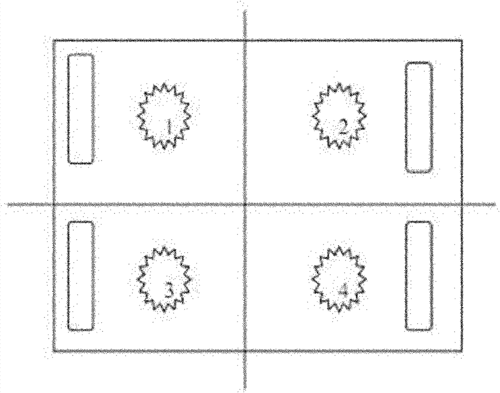
[0002] like figure 1 As shown, in the existing display mode of the screen menu, the screen menu is usually displayed in a fixed area of ​​the screen. For a general-purpose display device, since the display area is small, it can meet the needs of the user for convenient operation. However, for large-screen positioning interactive devices, due to the large display area of ​​the large screen, when the screen menu is placed and displayed on a fixed area of ​​the screen, for the operator, when performing interactive operations such as touch positioning, It is impossible to stand at a certain fixed position to realize the operation of all areas on the screen, so it is necessary to constantly move the position to be able to access the function menu on the screen to realize the corresponding operation, and the number of operations on the screen menu is less In some cases, it may be acceptable, but in the case of frequent operations through the menu, it will bring great inconvenience to the operator, and will affect the efficiency of interactive operations to a certain extent

Method used


Image

  • Tracking display method and device for screen menu
  • Tracking display method and device for screen menu
  • Tracking display method and device for screen menu

Examples


Embodiment 1

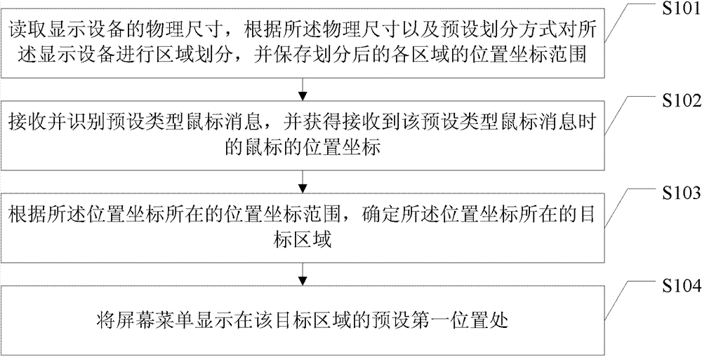
[0025] Such as figure 2 As shown, it is a schematic flow chart of Embodiment 1 of the method for tracking and displaying screen menus of the present invention, which includes steps:

[0026] Step S101: Read the physical size of the display device, divide the display device into regions according to the physical size and the preset division method, and save the position coordinate range of each region after division, and enter step S102;

[0027] Step S102: Receive and identify a preset type of mouse message, and obtain the position coordinates of the mouse when the preset type of mouse message is received, and proceed to step S103;

[0028] Step S103: According to the location coordinate range where the location coordinates are located, determine the target area where the location coordinates are located, and proceed to step S104;

[0029] Step S104: displaying the screen menu at a preset first position in the target area.

[0030] According to the solution in this embodime...

Embodiment 2

[0037] Such as Figure 4 As shown, it is a schematic flow chart of Embodiment 2 of the method for tracking and displaying screen menus of the present invention. In this embodiment, the difference from Embodiment 1 above is that the user may only be in one area within a period of time. In this case, there may be multiple actions of releasing the mouse. If the screen menu is refreshed frequently based on this, it may affect the user experience. Therefore, after the target area is determined, the A step of judging whether the target area is the area where the mouse is currently located.

[0038] Such as Figure 4 As shown, the method in this embodiment includes steps:

[0039] Step S201: Read the physical size of the display device, divide the display device into regions according to the physical size and the preset division method, and save the position coordinate range of each region after division, and enter step S202;

[0040] Step S202: Receive and identify a preset type ...

Embodiment 3

[0046] Such as Figure 5 As shown, it is a schematic flow chart of Embodiment 3 of the method for tracking and displaying screen menus of the present invention. In some cases, it may be necessary to operate at the first preset position of the set area or its boundary area. In this case, if the screen menu continues to be displayed within the area, it will inevitably affect the user's operation. , so by setting a new second preset position, the screen menu is moved to the second preset position, so as to improve user experience.

[0047] Such as Figure 5 As shown, the method in this embodiment includes steps:

[0048] Step S301: Read the physical size of the display device, divide the display device into regions according to the physical size and the preset division method, and save the position coordinate range of each region after division, and enter step S302;

[0049] Step S302: Receive and identify a preset type of mouse message, and obtain the position coordinates of ...


PUM


Abstract

The invention discloses a tracking display method and device for a screen menu. The method comprises the following steps: reading the physical size of display equipment, performing area division on the display equipment according to the physical size and a pre-set division way, and storing the position coordinate range of each divided area; receiving and identifying a pre-set type mouse message, and acquiring the position coordinates of a mouse when the pre-set type mouse message is received; determining a target area at which the position coordinates are located according to the position coordinate range at which the position coordinates are located; and displaying the screen menu at a pre-set first position of the target area. The invention realizes tracking display of the screen menu according to the mouse position when a user operates the mouse, facilitates the user operation on the screen menu, especially on the screen menu of a large-screen splicing wall, and improves the interactive operation efficiency.

Description

technical field [0001] The invention relates to the technical field of computer and image processing, in particular to a method for tracking and displaying a screen menu and a device for tracking and displaying the screen menu. Background technique [0002] Such as figure 1 As shown, in the existing display mode of the screen menu, the screen menu is usually displayed in a fixed area of ​​the screen. For a general-purpose display device, since the display area is small, it can meet the needs of the user for convenient operation. However, for large-screen positioning interactive devices, due to the large display area of ​​the large screen, when the screen menu is placed and displayed on a fixed area of ​​the screen, for the operator, when performing interactive operations such as touch positioning, It is impossible to stand at a certain fixed position to realize the operation of all areas on the screen, so it is necessary to constantly move the position to be able to access ...

Claims


Application Information

Patent Timeline
Patent Type & Authority Patents(China)
IPC IPC(8): G06F3/048G06F3/033G06F3/0482G06F3/0487
Inventor 卢如西白宝国段伟
Owner 南通卓效自动化有限公司
Learn More