Electronic visual laryngoscope

A laryngoscope and electronic technology, which is applied in the field of medical equipment, can solve the problems of not being suitable for viewing the screen of the display device, the range of deflection of the display device is limited, and the range of motion of the handle cannot be too large, so as to facilitate timely communication and improve self-positioning sex, the effect of protecting the throat tissue

Active Publication Date: 2011-03-16
ZHEJIANG UE MEDICAL
View PDF6 Cites 7 Cited by
  • Summary
  • Abstract
  • Description
  • Claims
  • Application Information

AI Technical Summary

Problems solved by technology

[0004] The display device in this laryngoscope is fixedly connected to the handle, that is, the display device does not move relative to the handle. In the middle, the handle can rotate relative to the lens, but limited by the chin of the human body, the range of motion of the handle cannot be too large. This motion is reflected on the display device, and the actual deflection range of the display device is quite limited. This is not very suitable for many people to watch the pictures in the display device, and it is also easy to cause damage to the inside of the patient's oral cavity, especially the larynx
Therefore, this kind of laryngoscope is inconvenient to participate in the communication between doctors during the consultation and treatment of patients, and it is also inconvenient for the communication between doctors and patients' families.

Method used


Image

  • Electronic visual laryngoscope
  • Electronic visual laryngoscope
  • Electronic visual laryngoscope

Examples


Embodiment Construction

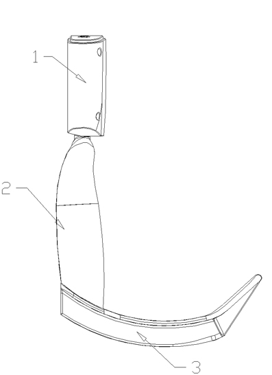
[0026] The structure of the electronic video laryngoscope of the present invention includes a display 1, a handle 2 and a lens 3, the lens 3 is connected to one end of the handle 2, the display 1 is movably connected to the other end of the handle 2 through a connection structure, and the front end of the lens 3 is provided There is a camera, and the camera is connected with the display 1 through wires. When the laryngoscope is in use, the handle 2 is used for holding by human hands, the lens 3 is used for suppressing the epiglottis, and the display 1 is used for displaying pictures taken by the camera.

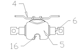
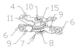
[0027] The main structure of the coupling structure is the coupling head 7 , and the structure of the coupling head 7 includes a coupling body A, a coupling body B and a connecting piece 9 . The connecting body A and the connecting body B can rotate relatively in the circumferential direction, and the two are relatively axially fixed. The relative circumferential rotation be...


PUM


Abstract

The invention discloses an electronic visual laryngoscope which solves the problem that in the current electronic visual laryngoscope, observation of the image in the display is affected because a display and a handle can not be relatively moved, thus the technical measure that the electronic visual laryngoscope is adopted. The electronic visual laryngoscope comprises a display, a handle and a lens, wherein the lens is connected with one end part of the handle; the display is movably connected with the other end part of the handle through a coupling head; the visual laryngoscope is characterized in that the coupling head comprises a coupling body A and a coupling body B which can be connected in a relative rotation manner; the coupling body A and the coupling body B are fixed relative to the axial direction; the coupling body A is connected with the display; a connecting piece is arranged on the coupling body B; the connecting piece can be rotatably connected with the other end part of the handle; a friction damping structure C is arranged between the coupling body A and the coupling body B; and a friction damping structure D is arranged between the connecting piece and the other end part of the handle.

Description

technical field [0001] The invention belongs to the technical field of medical devices, and in particular relates to a visualization tool used for pressing the epiglottis to display the internal situation of the larynx during human tracheal intubation or diagnosis and treatment of laryngeal diseases. technical background [0002] The laryngoscope can be used as a tool for exposing the glottis during tracheal intubation during induction of general anesthesia and on-site cardiopulmonary resuscitation. A laryngoscope is required. The function of the laryngoscope requires that the laryngoscope needs to be equipped with a display device, so that the condition of the patient's larynx can be clearly understood when performing corresponding medical activities. [0003] A Chinese utility model patent (patent number: 200820021599.7) discloses a laryngoscope, which includes a handle and a lens. The lens is movably connected to the handle. The inner cavity of the handle is provided wit...

Claims


Application Information

Patent Timeline
Patent Type & Authority Applications(China)
IPC IPC(8): A61B1/267A61B1/04A61B1/045
Inventor 王卫东李岳胜朱福斌
Owner ZHEJIANG UE MEDICAL
Why Eureka
Try Eureka