Motor cooling by feeder exhaust air

A waste gas and continuous paper technology, applied to printing machines, rotary printing machines, general parts of printing machinery, etc., can solve problems such as troublesome liquid circuits, small structural space, structural problems, etc., achieve effective cooling, save cooling devices, improve Derived effect of loss power

Inactive Publication Date: 2016-02-10
HEIDELBERGER DRUCKMASCHINEN AG
View PDF8 Cites 0 Cited by
  • Summary
  • Abstract
  • Description
  • Claims
  • Application Information

AI Technical Summary

Problems solved by technology

[0004] The disadvantage of the device in said publication DE 10 2004 024 971 A1 is that a complex liquid circuit must be present, which is correspondingly expensive and leads to structural problems when the installation space is small, as in a feeder

Method used


Image

  • Motor cooling by feeder exhaust air

Examples


Embodiment Construction

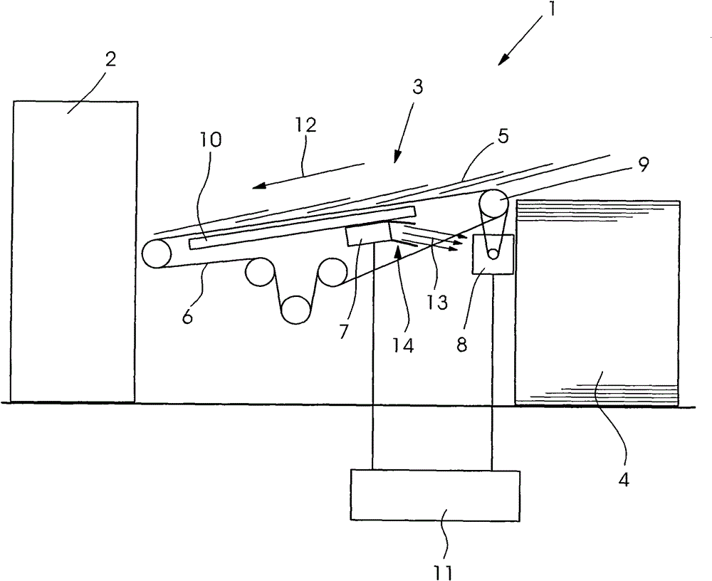
[0016] The sheet-fed printing press 1 has a plurality of printing units 2 , wherein the first printing unit 2 is supplied with a printing material 5 in sheet form via a feeding table 3 . The sheets 5 are removed from the paper stack 4 by means of a suction device (not shown here) and deposited in scales on the suction belt 6 . In this case, the speed of the suction belt 6 must correspond to the printing speed in the printing unit 2 . In the case of the sheet feeding table 3 shown in the figure, the drive of the suction belt 6 takes place by means of a drive motor 8 for said suction belt. For this purpose, the drive motor 8 is connected via a belt drive to the suction belt drive roller 9 and thus can move the suction belt 6 . The suction belt 6 is guided around a suction chamber 10 which continuously generates a vacuum and thus holds the scaly sheet 5 firmly on the perforated suction belt 6 . At the end of the sheet feeding table 3 , viewed in the sheet transport direction, t...


PUM


Abstract

The machine (1) has a drive motor (8) and a blower mechanism e.g. suction belt blower (7), producing low pressure or compressed air. The drive motor is subjected with exhaust air (13) of the suction belt blower. An air guidance mechanism (14) is provided between the suction belt blower and the drive motor that is cooled by a cooling device and the suction belt blower. The drive motor drives a suction belt (6) for sheet transportation in a feeder device of the machine. A hose is formed between the suction belt blower and the drive motor for the suction belt to guide the exhaust air.

Description

technical field [0001] The invention relates to a printing material processing machine with a drive motor and a blower device for generating working air for the machine. Background technique [0002] Sheet-fed rotary printing presses have a large number of blower air units which generate a blown air flow or a negative pressure flow in order to transport the sheet-form printing material in the machine. The blower air device is located in the printing press in particular in the vicinity of the transport cylinder, while the vacuum device is located in particular in the area of ​​the feeder and is arranged on the feeder table. To drive the suction belt in the area of ​​the feeder table, several drive motors can be provided. During operation, the drive motor generates heat, which has to be dissipated. At the same time, the installation space in the feeding table is limited, so that a complex cooling device for the drive motor of the suction belt cannot be considered. [0003] ...

Claims


Application Information

Patent Timeline
Patent Type & Authority Patents(China)
IPC IPC(8): B65H5/22B41F13/00
CPCB41F21/06B65H11/005B65H2301/5305B65H2406/3662
Inventor V·米勒O·诺娃拉
Owner HEIDELBERGER DRUCKMASCHINEN AG
Why Eureka
Try Eureka