
Rotary multi-way switching valve

A multi-channel switching and rotary technology, which is applied in the direction of multi-way valves, sliding valves, valve details, etc., can solve the problems of inability to realize multi-channel multi-state control, restricting the number of valve ports, and inability to realize refrigerator refrigerant combinations, etc.

Inactive Publication Date: 2011-03-16
赵肖运
View PDF6 Cites 16 Cited by
  • Summary
  • Abstract
  • Description
  • Claims
  • Application Information

AI Technical Summary

Problems solved by technology

[0002] With the continuous improvement of the quality of life, high-end household refrigerators are required to achieve multi-section temperature control and soft freezing technology that is safer for food. The existing two-position three-way refrigerator solenoid valve cannot meet the above requirements. The existing two The three-way refrigerator solenoid valve is driven by an electromagnetic coil, and the valve core moves in a straight line with only two working positions, which cannot realize multi-channel and multi-state control. The valve ports of other rotary solenoid valves with similar structures are distributed on the same diameter circle, so that Only one valve port state can be set at the same rotation angle, which restricts the setting of the number of valve ports, reduces the number of control channels and control states, and cannot realize the combination of various control states for refrigerator refrigerants

Method used


Image

  • Rotary multi-way switching valve
  • Rotary multi-way switching valve
  • Rotary multi-way switching valve

Examples


Embodiment Construction

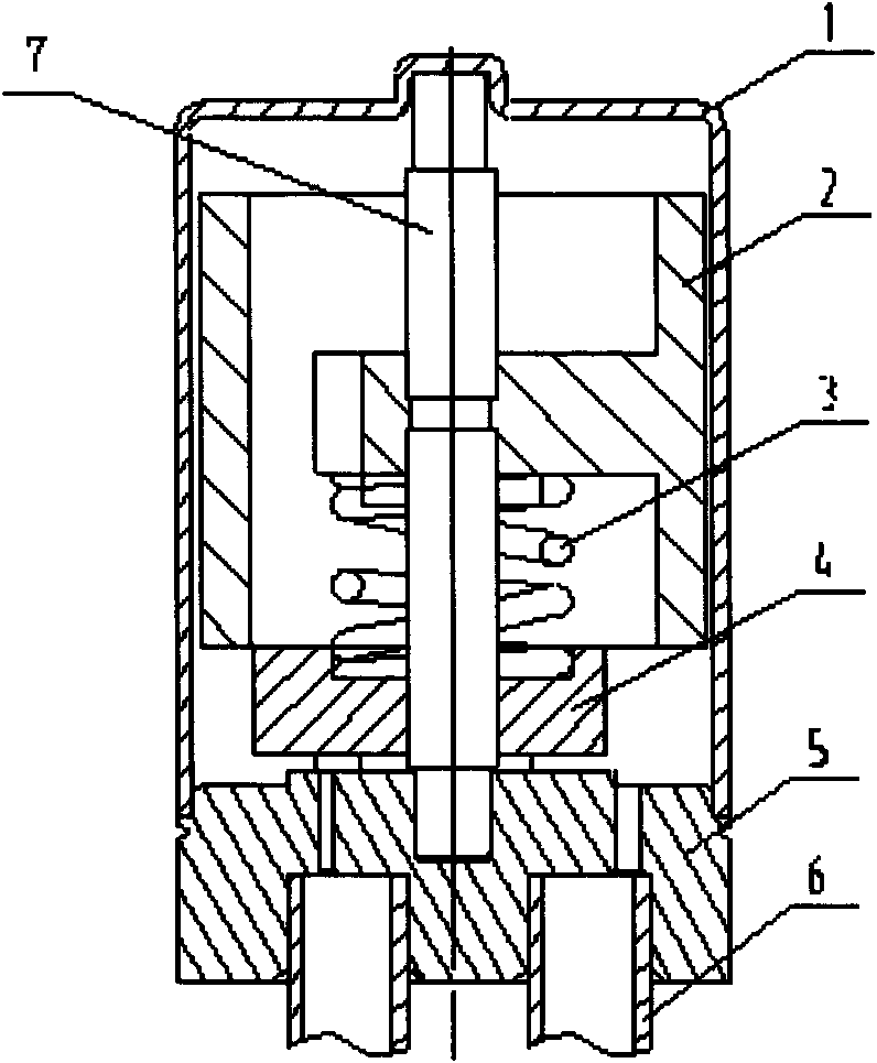
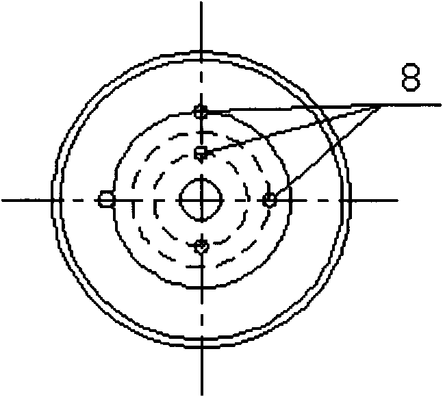
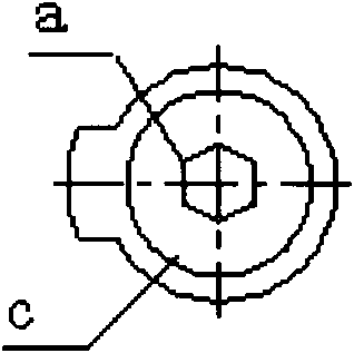
[0016] Such as figure 1 As shown, a rotary multi-way switching valve includes an outer cover 1, a shaft 7, a rotor 2, and a valve seat 5 at the lower part of the rotor. The rotor 2 is sleeved on the shaft 7 and a slider 4 is provided on the lower end surface of the rotor 2. The upper end surface of the valve seat 5 is provided with valve ports 8 communicating with the inlet and outlet connecting pipes 6 on multiple concentric circles, and at least two valve ports are on the same radial direction, and one or more valve ports are provided on each circumference, sliding The axial bottom end surface of the block 4 is provided with at least two boss planes b with different radii that are matched and sealed with the corresponding valve ports. Stop block, the switching valve is driven by a stepping motor, the rotating magnetic field force generated by the electronic coil of the stepping motor acts on the rotor 2, and the rotor 2 transmits the rotational torque to the slider 4 connect...


PUM


Abstract

The invention discloses a rotary multi-way switching valve which is driven by a stepping motor and comprises an outer housing, a shaft, a rotor and a valve seat at the lower part of the rotor, wherein the rotor is sheathed on the shaft, a sliding blocks is arranged on the lower end surface of the rotor, the sliding block can rotate along with the rotor under the drive the stepping motor, valve ports communicated with inlet and outlet connecting pipes are arranged on a plurality of concentric circumferences of the upper end surface of the valve seat, at least two valve ports are arranged in the same radial direction, one or more valve ports are arranged on each circumference, at least two boss planes which have different radii and are matched with the corresponding valve ports and sealed are arranged on the axial bottom end surface of the sliding block, a pressure spring is arranged on the upper end surface of the sliding block, and the upper end of the pressure spring is sheathed in the lower end of the rotor. The rotary multi-way switching valve can simultaneously carry out switching control on a plurality of the valve ports when a valve core stays at a certain angle and realize the combination of various states of a refrigerant.

Description

technical field [0001] The invention relates to a rotary multi-way switching valve, which is mainly used in a refrigeration system for high-end household refrigerators to control different flow directions and sizes of refrigerants. Background technique [0002] With the continuous improvement of the quality of life, high-end household refrigerators are required to achieve multi-section temperature control and soft freezing technology that is safer for food. The existing two-position three-way refrigerator solenoid valve cannot meet the above requirements. The existing two The three-way refrigerator solenoid valve is driven by an electromagnetic coil, and the valve core moves in a straight line with only two working positions, which cannot realize multi-channel and multi-state control. The valve ports of other rotary solenoid valves with similar structures are distributed on the same diameter circle, so that Only one valve port state can be set at the same rotation angle, thu...

Claims


Application Information

Patent Timeline
Patent Type & Authority Applications(China)
IPC IPC(8): F16K11/074F16K31/04F16K3/08F16K3/30
Inventor 裘慧祥王伟伟
Owner 赵肖运
Learn More