Lyophilizer

A technology of freeze-drying machine and freeze-drying box, which is applied in the field of freeze-drying machines, can solve the problems of cumbersome operation, complex structure, poor equipment correlation, etc., and achieve the effect of good effect, good integrity and easy operation

Inactive Publication Date: 2011-03-16
兆丰华生物科技(福州)有限公司
View PDF6 Cites 3 Cited by
  • Summary
  • Abstract
  • Description
  • Claims
  • Application Information

AI Technical Summary

Problems solved by technology

However, most of the existing freeze dryers are bulky, complex in structure, cumbersome in operation, and poorly connected to equipment

Method used


Image

  • Lyophilizer
  • Lyophilizer

Examples


Embodiment Construction

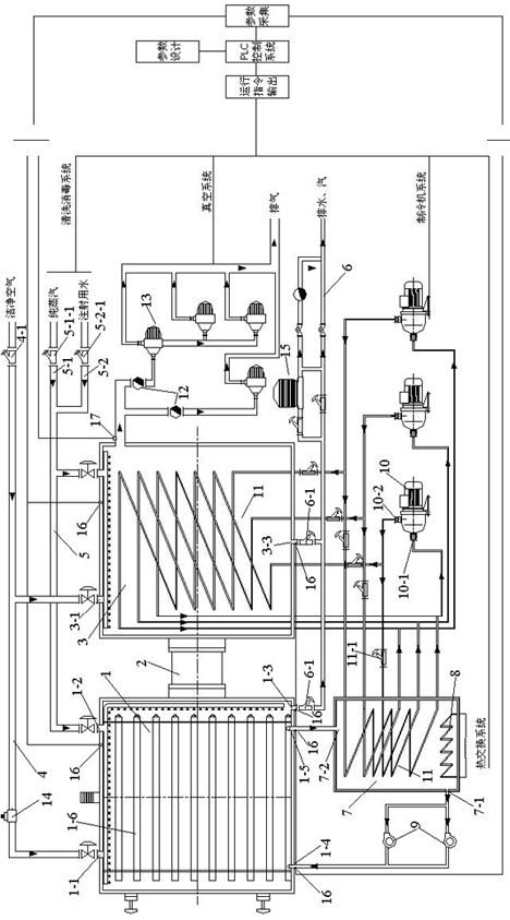
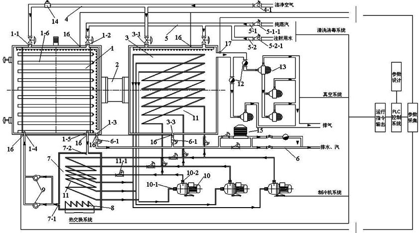
[0007] refer to figure 1 , a freeze-drying machine, comprising a freeze-drying box 1 with liftable plates 1-6 inside, a condensation trap 3 connected to the freeze-drying box 1 through a septum valve 2, a compressor 10, and the freeze-drying box 1 and the air inlets 1-1 and 3-1 of the condensate catcher 3 are connected with a gas supply pipeline 4, and the freeze-drying box 1 and the cleaning ports 1-2 and 3-2 of the condensate catcher 3 are connected There is a cleaning pipeline 5, and the drain outlets 1-3 and 3-3 of the freeze-drying box 1 and the condensate catcher 3 are connected with a drain pipeline 6 through a discharge angle seat valve 6-1.

[0008] The above-mentioned freeze-drying box 1 is also connected with a silicon oil tank 7, and the silicon oil tank 7 is respectively provided with a refrigeration pipeline 11 for providing a cooling source for the silicone oil and a heater 8 for providing heat, and the oil outlet 7 of the silicon oil tank 7 -1 is connected wit...


PUM


Abstract

The invention relates to a lyophilizer, comprising a lyophilisation box with lifting board layers inside, a condensing water catcher connected with the lyophilisation box by a middle separating valve and a compressor. The lyophilizer is characterized in that air inlets of the lyophilisation box and the condensing water catcher are connected with an air supply pipe; washing openings of the lyophilisation box and the condensing water catcher are connected with a washing pipe; and discharge outlets of the lyophilisation box and the condensing water catcher are connected with a discharge pipe by discharge angle seat valves. The lyophilizer has good integrity and good lyophilisation effect and is convenient to control in the production process.

Description

technical field [0001] The invention relates to a freeze dryer, which can be applied to the fields of biological engineering, pharmaceutical industry, food industry, material science, deep processing of agricultural and sideline products and the like. Background technique [0002] The vacuum freeze-drying technology that originated in the 1920s has made great progress in the last 20 years after decades of ups and downs. In the 21st century, vacuum freeze-drying technology has become more and more popular due to its incomparable advantages over other drying methods. In addition to being widely used in the fields of medicine, biological products, food, blood products and active substances, its application scale and field Still expanding. However, most of the existing lyophilizers are bulky, complex in structure, cumbersome in operation, and poorly related to equipment. Therefore, how to solve the above problems is the research purpose of the present invention. Contents of ...

Claims


Application Information

Patent Timeline
Patent Type & Authority Applications(China)
IPC IPC(8): F26B5/06
Inventor 陈先进
Owner 兆丰华生物科技(福州)有限公司
Why Eureka
Try Eureka