
Bender transducer for generating electrical energy from mechanical deformations

A mechanical deformation, transducer technology, applied in the direction of generator/motor, piezoelectric device/electrostrictive device, piezoelectric/electrostrictive/magnetostrictive device, etc., to improve stability, improve reliability, The effect of simple and reliable contact

Active Publication Date: 2011-03-23
ROBERT BOSCH GMBH
View PDF4 Cites 6 Cited by
  • Summary
  • Abstract
  • Description
  • Claims
  • Application Information

AI Technical Summary

Problems solved by technology

However, these wire connections are likewise subjected to the mechanical stresses that occur and have only a limited durability against repeated deformations

Method used


Image

  • Bender transducer for generating electrical energy from mechanical deformations
  • Bender transducer for generating electrical energy from mechanical deformations
  • Bender transducer for generating electrical energy from mechanical deformations

Examples


Embodiment Construction

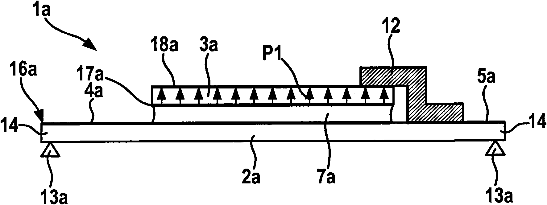
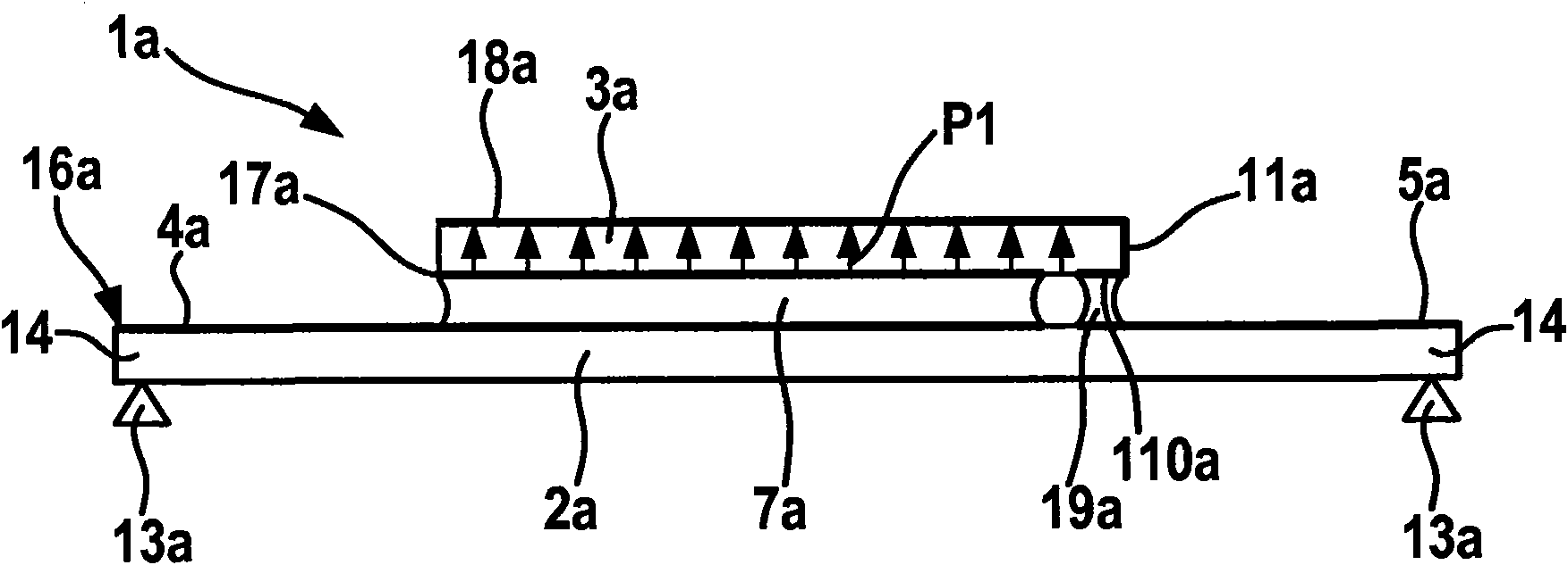
[0026] one in figure 1 The bending transducer 1a shown in includes a deformable carrier 2a and a piezoelectric element 3a. The carrier 2a has a planar and plane-parallel shape and is elastically deformable; here, the carrier is supported or clamped on the support elements 13a with its two opposite side regions 14, so that Deformation between, especially bending deformation. The first connecting electrode 4 a and the second connecting electrode 5 a are applied as part of a structured, electrically conductive layer, in particular a metal layer, on the upper side 16 a of the carrier 2 a by means of a photolithographic process or an etching process, and along the lateral, side Extend outward in the direction.

[0027] The piezo element 3 a is also planar; it is made in particular of a ceramic material and has a consistent polarity direction P1 in this embodiment. The piezoelectric element has a first lower electrode 17a on its lower side serving as a connection side and a first...


PUM


Abstract

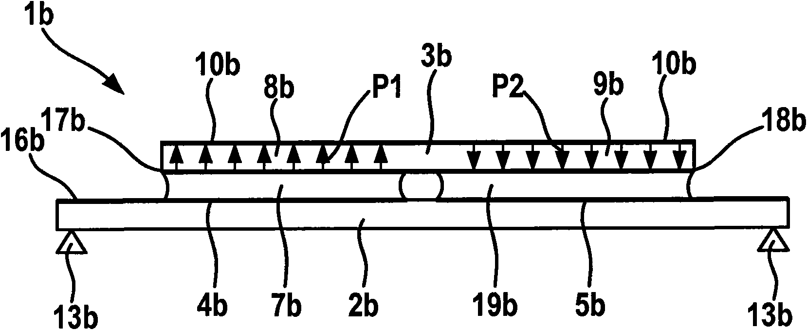
The invention relates to a bender transducer (1b) for generating electrical energy from mechanical deformations, said bender transducer comprising: a deformable support device (2b) on which a first connecting electrode (4b) and a second connecting electrode (5b) are configured, a piezoelectric element (3b) having at least one first electrode (17b) and a second electrode (18b) and being fastened to the support device (2b), the first connecting electrode (4b) being contacted with the first electrode (17b) of the piezoelectric element (3b) and the second connecting electrode (5b) with the second electrode (18b) of the piezoelectric element (3b). The first connecting electrode (4b) and / or the second connecting electrode (5b) is applied to the support device (2b) as a structured, conductive layer in at least some sections thereof. In particular, the two connecting electrodes (4b, 5b) can be configured as sections of a common layer. The invention further relates to a circuit module having a self-sufficient energy supply and a bender transducer of the above type.

Description

Background technique [0001] Piezoelectric transducers are used in particular in the field of sensor technology and actuation technology. In order to convert the mechanical stresses generated in the deformed structure, the piezoelectric element is usually coupled directly to a carrier element or carrier structure, wherein the carrier structure can also be a second piezoelectric element (known as piezoelectric bimorph ). In this case, the piezo element has two electrodes for introducing and discharging charge to the interface electronics. In this case, the electrodes are usually formed on opposite sides of the mostly flat piezoelectric element. [0002] For example, DE 10 2005 062 872 A1 discloses a device for rolling detection of a wheel, in which a piezoelectric element is contacted on a chip carrier with electrodes formed on its opposite sides, wherein the upper electrode of the piezoelectric element is connected via a key The bonding wires are contacted and the chip carri...

Claims


Application Information

Patent Timeline
Patent Type & Authority Applications(China)
IPC IPC(8): H01L41/113H01L41/09H02N2/18B60C23/04H10N30/30H10N30/20H10N30/87
CPCH01L41/1134B60C23/0411H01L41/047H10N30/875H10N30/304
Inventor M·霍尔蒂希T·潘内克G·克勒特M·凯克
Owner ROBERT BOSCH GMBH
Learn More