A mold clamping device and an operating method of the mold clamping device

A mold clamping device and action technology, applied in the field of mold clamping devices, can solve the problems of time-consuming supply, inability to shorten the forming cycle time, and inability to compact the hydraulic circuit, and achieve the effect of shortening the forming cycle

Active Publication Date: 2011-03-30
JAPAN STEEL WORKS LTD
View PDF7 Cites 2 Cited by
  • Summary
  • Abstract
  • Description
  • Claims
  • Application Information

AI Technical Summary

Problems solved by technology

[0010] Although the techniques of the above-mentioned Patent Document 4 and Patent Document 5 have a structure in which the first pressure cylinder chamber of the mold clamping side of the mold clamping pressure cylinder communicates with the second pressure cylinder chamber of the mold opening side, etc., due to Both the mold clamping side and the mold opening side do not have small-diameter pressure cylinder chambers, so when the mold clamping pressure cylinder is moved in both directions, it cannot be moved with a small flow rate of hydraulic oil, and the supply of hydraulic oil to the oil chamber is expensive. time, so the total forming cycle time cannot be shortened
Alternatively, if the total molding cycle time is to be shortened, it is necessary to prepare a pump or valve of the hydraulic circuit in a structure capable of supplying a large amount of hydraulic oil in a short time, and the above-mentioned hydraulic circuit cannot be compacted.

Method used


Image

  • A mold clamping device and an operating method of the mold clamping device
  • A mold clamping device and an operating method of the mold clamping device
  • A mold clamping device and an operating method of the mold clamping device

Examples


Embodiment Construction

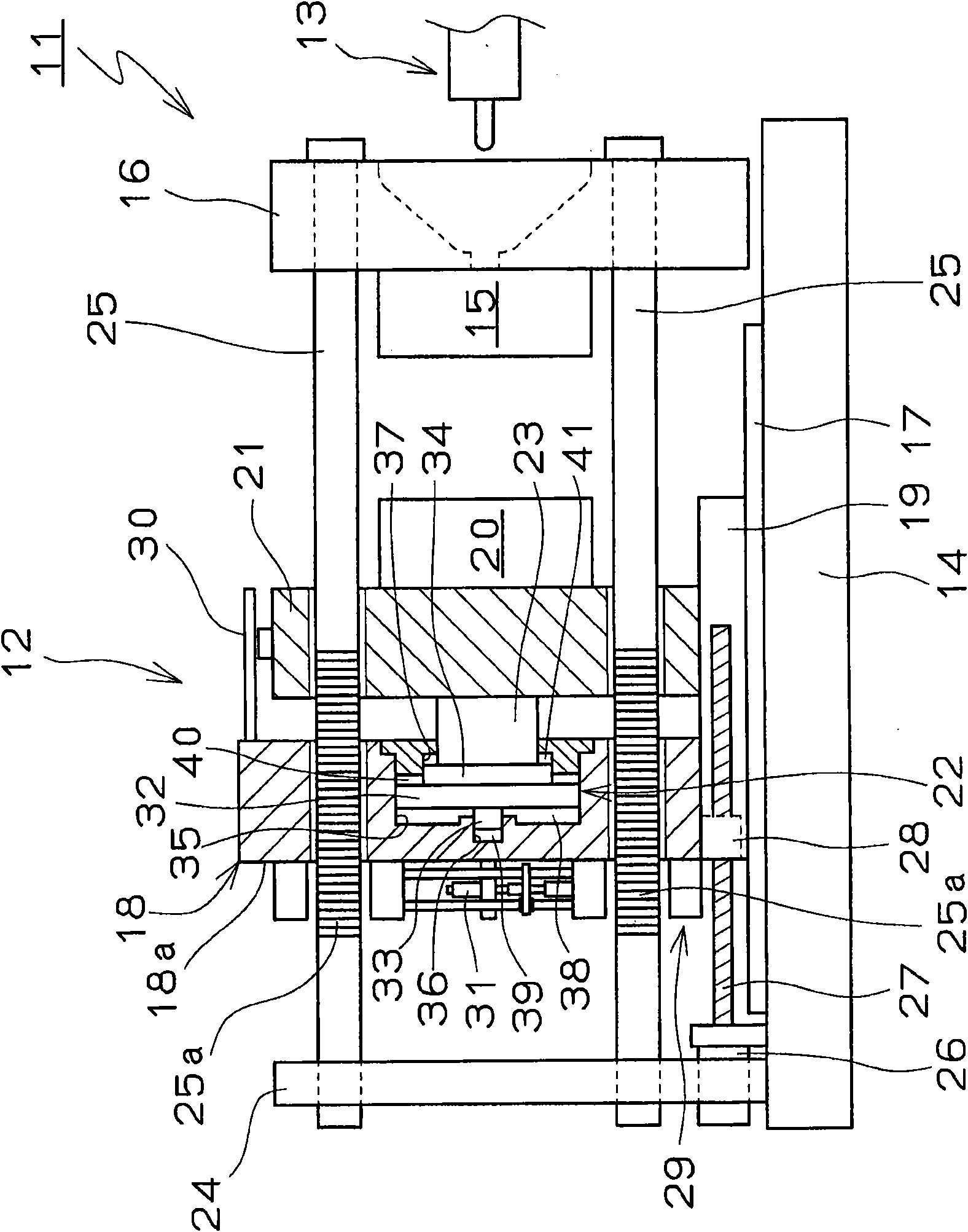
[0042] refer to figure 1 The mold clamping device of the injection molding machine according to the embodiment of the present invention will be described. The injection molding machine 11 basically includes a mold clamping device 12 provided on one side and an injection device 13 provided on the other side. When the mold clamping device 12 is described, a fixed plate 16 on which the fixed metal mold 15 is mounted is erected on the other side (injection device side) of the base 14 . Further, on the base 14, a linear motion guide 17 is fixed toward the mold opening and closing direction, and a movable mold clamping plate 18 is provided on the linear motion guide 17 so as to be movable in the mold opening and closing direction. Furthermore, on the movable mold clamping plate 18, a stand 19 as a foot portion is integrally fixed toward the fixed plate side, and on the stand 19, a mounting bracket is provided so as to be movable relative to the movable mold clamping plate 18 in the...


PUM


Abstract

Provided is a mold clamping device by using a mold clamping pressure cylinder, capable of rapidly moving the mold clamping pressure cylinder toward two directions without size maximization of pumps or valves in a liquid pressure loop so as to shorten a period after clamping a locknut and a locking part. The mold clamping device (12), in which a movable metal mold (20) is close to or conjoined to a fixed metal mold (15) by a mold switching mechanism (26) and the mold is clamped by the mold clamping pressure cylinder (22) after clamping the locknut (29) and the locking part (25), is provided with a first pressure cylinder chamber (38) for mold clamping, a second pressure cylinder chamber (39) and a third pressure cylinder chamber (41) which pressure-receiving areas are less than that of a first pressure cylinder chamber (38), by using a mold clamping piston (32) of a mold clamping pressure cylinder (22) as a boundary.

Description

technical field [0001] The present invention relates to a mold clamping device and a mold clamping device which closes or abuts a movable metal mold relative to a fixed metal mold by a mold opening and closing mechanism, locks a half nut and a locking part, and performs mold clamping by a mold clamping pressure cylinder. The operation method of the model device. Background technique [0002] As a mold clamping device used in an injection molding machine, there are devices that perform mold opening and closing and mold clamping by the same mechanism like a toggle mechanism, and devices that allow a movable metal mold to approach or touch a fixed metal mold by a mold opening and closing mechanism. A mold clamping device that is connected to the mold clamping pressure cylinder after the half nut is locked with the locking part. The structures described in Patent Document 1 to Patent Document 5 are known as the latter type using a half nut and a mold clamping cylinder. of Pate...

Claims


Application Information

Patent Timeline
IPC IPC(8): B29C45/67
CPCB29C45/641B29C45/67
Inventor 神野镇绪林真二
Owner JAPAN STEEL WORKS LTD
Why Eureka
Try Eureka