Heat insulating mold, mold component, molding machine, and method for manufacturing the heat insulating mold

A mold and thermal insulation technology, applied in the field of thermal insulation molds, can solve the problems of abrasion of the thermal insulation layer, expansion or contraction of the die, and reduced bonding stability.

Inactive Publication Date: 2009-10-07
SUMITOMO HEAVY IND LTD
View PDF1 Cites 2 Cited by
  • Summary
  • Abstract
  • Description
  • Claims
  • Application Information

AI Technical Summary

Problems solved by technology

[0010] However, in the heat insulating mold of the above-mentioned prior art, the durability of the heat insulating layer is lowered due to the selected heat insulating material and the method of forming the heat insulating layer, etc.
[0011] For example, although it is conceivable to form a heat insulating layer made of a polymer material on the surface of the mold main body that is in contact with the mold insert, as molding is repeated, expansion and contraction caused by heating cycles make the surface of the heat insulating layer contact with the mold main body. Part of the face is rubbed and the insulation is worn away
[0012] Furthermore, in the heat insulating layer described in Patent Document 1, since gaps are formed, roughness corresponding to the gaps will appear on the surface even if it is polished.
As a result, as the temperature of the resin changes during the molding process, expansion or contraction of the stamper may occur, and scratches may be formed on the back of the stamper
Also, in order to prevent the formation of scratches, DLC coating can be considered, but if DLC coating is applied on a rough surface, the adhesion stability will be reduced

Method used


Image

  • Heat insulating mold, mold component, molding machine, and method for manufacturing the heat insulating mold
  • Heat insulating mold, mold component, molding machine, and method for manufacturing the heat insulating mold
  • Heat insulating mold, mold component, molding machine, and method for manufacturing the heat insulating mold

Examples


Embodiment Construction

[0033] Embodiments of the present invention will be described in detail below with reference to the drawings. In this case, an injection molding machine as a molding machine will be described.

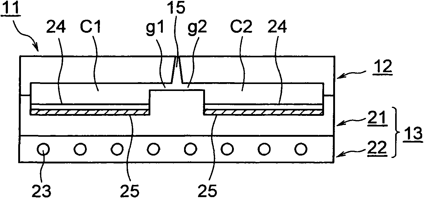
[0034] figure 1 It is a cross-sectional view of the heat insulating mold according to the first embodiment of the present invention.

[0035] In the figure, 11 is a mold device as a heat-insulating mold for forming molded products such as light guide plates and disk substrates, 12 is a fixed mold as a first mold, and 13 is a first mold that is freely arranged on the fixed mold 12 to advance and retreat. 2 Movable molds of the mold, C1 and C2 are cavity spaces formed between the fixed mold 12 and the movable mold 13 accompanying mold closing.

[0036] And, the above-mentioned movable mold 13 is provided with the upper plate 21 as a template and as the first mold part, and the lower plate 22 as the carrier plate for carrying the upper plate 21 and as the second mold part; On the surfa...


PUM

PropertyMeasurementUnit
surface roughnessaaaaaaaaaa

Abstract

This invention provides a heat insulating mold, a mold component, a molding machine and a method for manufacturing the heat insulating mold, which can realize shortened molding cycles and improved durability of heat insulating layer (25). The heat insulating mold comprises a mold plate and a transfer member mounted on the mold plate provided with a transfer face having a fine concavoconvex pattern on a face opposite to cavity spaces (C1, C2). The heat insulating layer (25) having a densified surface is formed on the mold plate in its face abutted against the transfer member. Since the heat insulating layer (25) is formed on the mold plate in its face abutted against the transfer member, the temperature of the molding material filled into the cavity spaces (C1, C2) is temporarily held by the heat insulating layer (25). As a result, the growth and development of the surface hardening layer is delayed, and the pattern transfer of the transfer face can be finished in the delayed period. Since the surface of the insulating layer (25) is densified, the surface of the heat insulating layer (25) can be smoothened to a very high level. Further, the durability of the heat insulating layer (25) can be improved.

Description

technical field [0001] The present invention relates to a heat-insulating mould, a mold part, a forming machine and a method of manufacturing a heat-insulating mould. Background technique [0002] Conventionally, in a molding machine such as an injection molding machine, resin melted in a heating cylinder is filled into a cavity space in a mold device, cooled and solidified in the cavity space, and molded into a molded product. [0003] The above-mentioned injection molding machine has a mold device, a mold clamping device, and an injection device. The injection device has a heating cylinder that heats and melts the resin, and is installed at the front end of the heating cylinder. An injection nozzle that injects the molten resin is free to rotate and can move forward and backward. Screws and the like arranged in the above-mentioned heating cylinder. In addition, the above-mentioned mold device has a fixed mold and a movable mold, and by using the above-mentioned mold clamp...

Claims


Application Information

Patent Timeline
Patent Type & Authority Applications(China)
IPC IPC(8): B29C33/42B29C33/38B29C45/37
CPCB29C45/263B29L2017/005B29C45/37B29C2045/2636B29C33/42B29C33/38
Inventor 平田彻
Owner SUMITOMO HEAVY IND LTD
Why Eureka
Try Eureka