Fuel supply device

Active Publication Date: 2013-12-19
HONDA MOTOR CO LTD
View PDF0 Cites 12 Cited by
  • Summary
  • Abstract
  • Description
  • Claims
  • Application Information

AI Technical Summary

Benefits of technology

[0017]According to the fourth aspect of the invention, when receiving the internal combustion engine stop command, in the case where the inlet temperature of the separator is equal to or higher than a sufficient temperature for separating the fuel, the internal combustion engine is not stopped immediately, the raw fuel is sent into the raw fuel path by the raw fuel discharge device, and the separatio

Problems solved by technology

Performance of separating the fuel (transmission rate) depends on a temperature of the separator, so that adjustment of the temperature of the separator becomes one of important problems of the fuel supply device.
However, there is a problem that, even when the fuel

Method used


Image

  • Fuel supply device
  • Fuel supply device
  • Fuel supply device

Examples


Example

[0026](Structure)

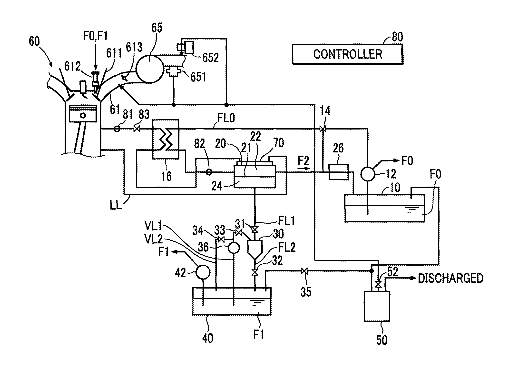
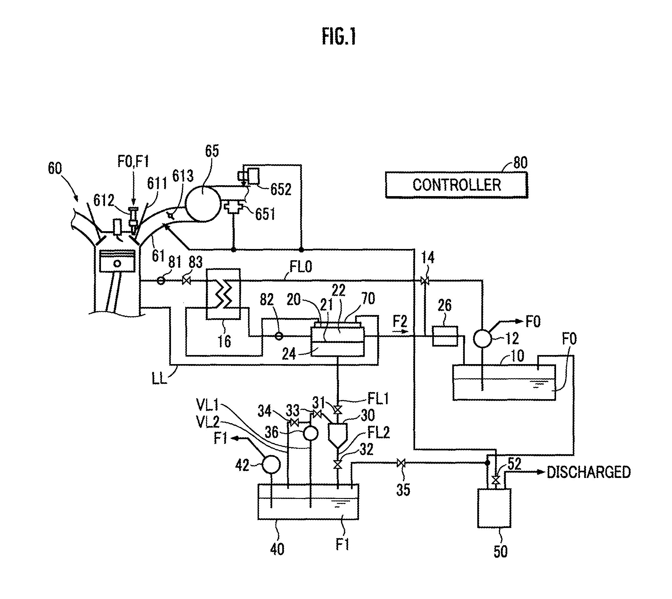
[0027]The fuel supply device illustrated in FIG. 1 includes a raw fuel tank 10, a separator 20, a condenser 30, a first fuel tank 40, a canister 50, and a controller (or an electronic control unit [ECU]) 80. The fuel supply device is mounted on a vehicle and is configured to supply fuel to an internal combustion engine 60, which is also mounted on the vehicle.

[0028]The raw fuel tank 10 stores normal or commercially-available gasoline, which is supplied through a fill opening, as a raw fuel F0. The raw fuel F0 stored in the raw fuel tank 10 is increased in pressure up to a specified pressure by a high-pressure supply pump 12 (a raw fuel discharge device) and then supplied to the internal combustion engine 60 (not illustrated).

[0029]Moreover, after the increase in pressure up to the specified pressure by the high-pressure supply pump 12, the raw fuel F0 is heated by a heater 16 and then fed into the separator 20 via the raw fuel path FL0. A raw fuel temperature sensor...


PUM


Abstract

A device capable of supplying an internal combustion engine 60 with a first fuel F1 of a high octane number fuel, and a second fuel F2 of a low octane number fuel or a raw fuel F0. The device is equipped with a cooling medium circulating path LL configured to perform heat exchange between a cooling medium for cooling the internal combustion engine 60 and a separator 20. The device adjusts a flow rate of the cooling medium in the cooling medium circulating path LL, so that a separator temperature T1 is contained in a predetermined temperature range, according to T1, a raw fuel temperature T2 and a cooling medium temperature T3.

Description

BACKGROUND OF THE INVENTION[0001]1. Field of the Invention[0002]The present invention relates to a technique for supplying fuel to an internal combustion engine.[0003]2. Description of the Related Art[0004]There has been known a fuel supply device which separates a raw fuel and generate a fuel having characteristics different from the raw fuel, and which supplies these fuels. As such fuel supply device, for example, there is a device equipped with a separator which separates a raw fuel into a high octane number fuel having higher octane number than the raw fuel and a low octane number fuel having lower octane number than the raw fuel (refer to Japanese Patent Application Laid-Open No. 2007-231818, and Japanese Patent Application Laid-Open No. 2004-522039).[0005]Performance of separating the fuel (transmission rate) depends on a temperature of the separator, so that adjustment of the temperature of the separator becomes one of important problems of the fuel supply device. On this poi...

Claims


Application Information

Patent Timeline
IPC IPC(8): F02M53/04
CPCF02D19/0649F02M53/04Y02T10/30
Inventor SHIGETOYO, KENJIKUDO, HIROTSUGUCHISHIMA, HIROSHIASANUMA, MASAHIKO
Owner HONDA MOTOR CO LTD
Why Eureka
Try Eureka