Disc master, disc master manufacturing method, stamper, disc substrate, optical disc, and optical disc manufacturing method

a technology of disc master and manufacturing method, which is applied in the direction of instruments, applications, photomechanical equipment, etc., can solve the problems of degrading separation performance and increasing adhesion between the substrate and the stamper, and achieve the effect of improving separation performance, maintaining signal characteristics, and improving separation performance between the stamper and the disc substra

Inactive Publication Date: 2010-02-11
SONY CORP
View PDF10 Cites 0 Cited by
  • Summary
  • Abstract
  • Description
  • Claims
  • Application Information

AI Technical Summary

Benefits of technology

[0043]More specifically, in the disc master, a boundary portion between a recessed portion and a non-recessed portion includes a small protrusion which protrudes from a flat surface of the non-recessed portion. The shape of the disc master is inversely transferred to the stamper, and the shape of the stamper is inversely transferred to the disc substrate. The separation performance is improved and the signal characteristics are maintained due to the shape of the boundary portion.
[0044]According to the present invention, in the process of manufacturing the optical disc, the separation performance between the stamper and the disc substrate can be improved. In addition, satisfactory signal characteristics can be maintained in the manufactured optical disc.

Problems solved by technology

However, when sufficient cooling and pressurization are performed to improve the transferability, there is a problem that adhesion between the substrate and the stamper increases and the separation performance will be degraded.

Method used


Image

  • Disc master, disc master manufacturing method, stamper, disc substrate, optical disc, and optical disc manufacturing method
  • Disc master, disc master manufacturing method, stamper, disc substrate, optical disc, and optical disc manufacturing method
  • Disc master, disc master manufacturing method, stamper, disc substrate, optical disc, and optical disc manufacturing method

Examples


Embodiment Construction

[0055]Hereinafter, an embodiment of the present invention will be described.

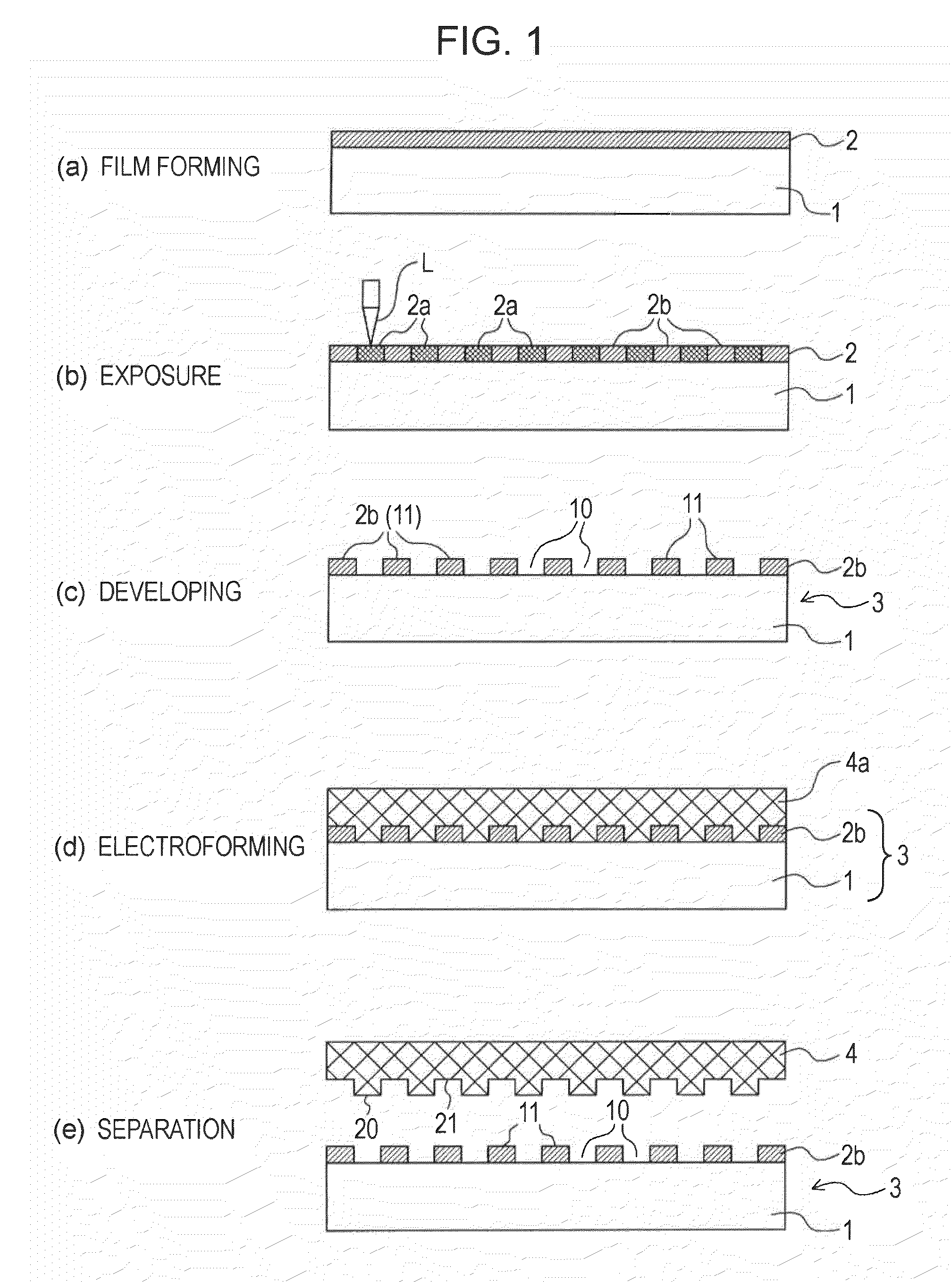
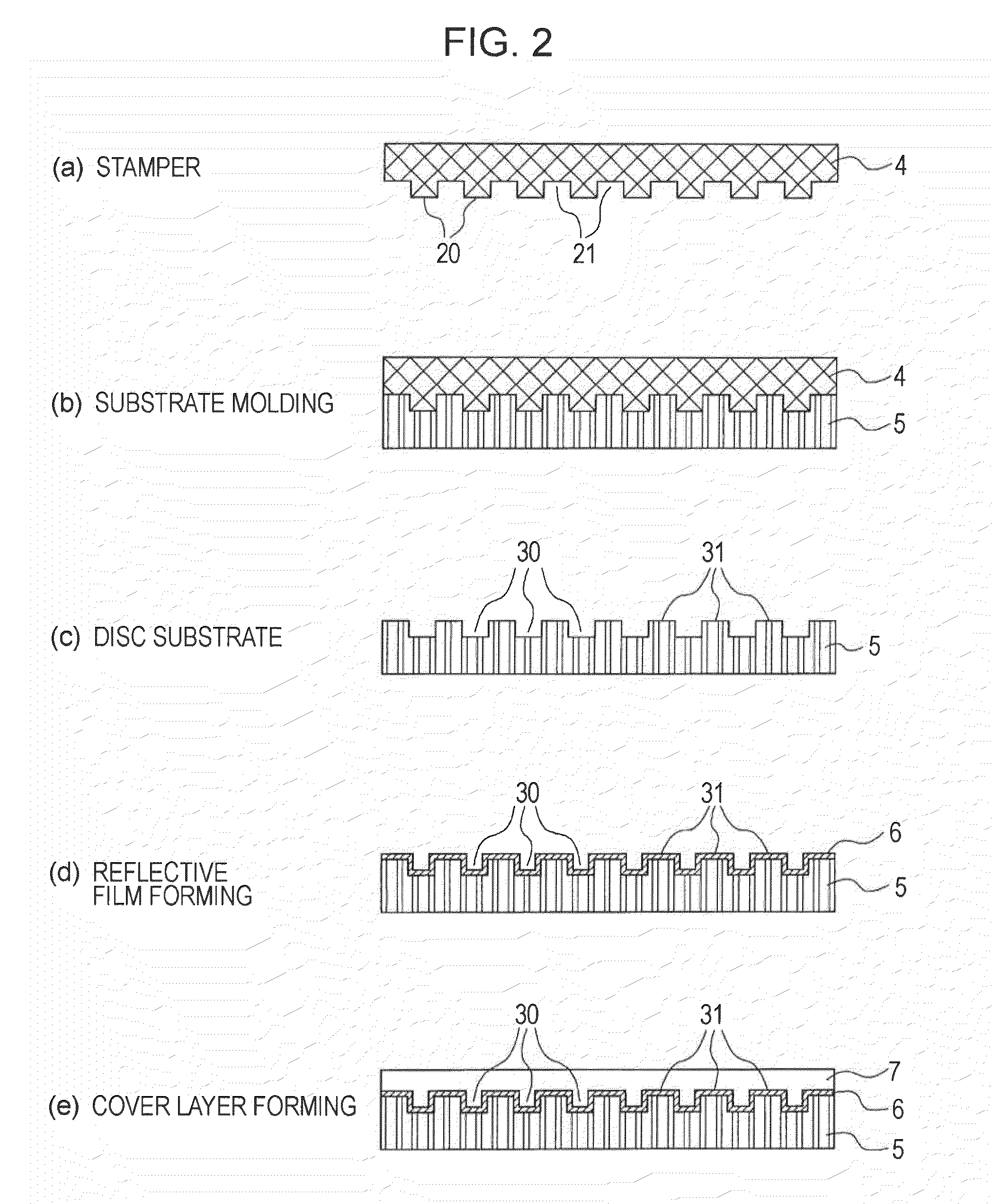
[0056]First, the overall manufacturing process of an optical disc will be described with reference to FIGS. 1 and 2.

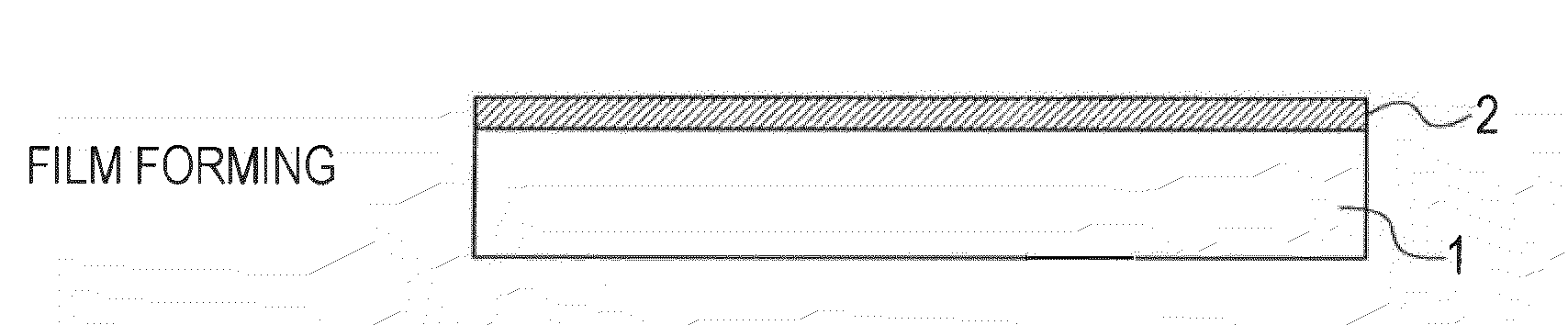
[0057]FIG. 1(a) shows the state in which a resist film 2 is formed on a master substrate 1 for forming a disc master.

[0058]The master substrate 1 is, for example, a glass substrate or a silicon wafer substrate.

[0059]In the film forming step, the resist layer 2 made of an inorganic resist material is uniformly formed on the master substrate 1 by sputtering.

[0060]More specifically, a film of inorganic resist is formed using a film-forming device (sputtering device) on the master substrate 1 made of glass or silicon wafer. Thus, a film with a sufficient thickness for forming pits or grooves with a desired height is obtained.

[0061]In the sputtering device, an alloy oxide of a transition metal, for example, is used as a target material. With regard to a film-forming method, DC or RF sputtering is us...


PUM

PropertyMeasurementUnit
wavelengthaaaaaaaaaa
heightaaaaaaaaaa
heightaaaaaaaaaa

Abstract

In a process of manufacturing a disc master, a stamper, a disc substrate, and an optical disc, separation performance between the stamper and the disc substrate and maintenance of satisfactory signal characteristics after the optical disc is manufactured are taken into consideration in the step of manufacturing the disc master. In the disc master, a boundary portion between a recessed portion and a non-recessed portion includes a small protrusion which protrudes from a flat surface of the non-recessed portion. The shape of the disc master is inversely transferred to the stamper, and the shape of the stamper is inversely transferred to the disc substrate. The separation performance is improved and the signal characteristics are maintained due to the shape of the boundary portion.

Description

TECHNICAL FIELD[0001]The present invention relates to a disc master, a disc master manufacturing method, a stamper, a disc substrate, an optical disc, and an optical disc manufacturing method.BACKGROUND ARTPatent Document 1: Japanese Unexamined Patent Application Publication No. 2004-152465Patent Document 2: Japanese Unexamined Patent Application Publication No. 2-150325[0002]Conventionally, in a general optical disc manufacturing method, first, a disc master is manufactured. Then, a stamper is manufactured using the disc master, and disc substrates are mass-produced using the stamper. A layered structure including a reflective film, a cover layer, etc., is formed on the mass-produced disc substrates. Thus, optical discs are completed.[0003]Here, first, the disc master is formed such that the disc master has a recess-projection pattern for forming a pit / land structure which defines information signal lines, or a recess-projection pattern for forming a groove / land structure which def...

Claims


Application Information

Patent Timeline
Patent Type & Authority Applications(United States)
IPC IPC(8): B32B3/02B29C59/02B29C33/40G11B7/24076G11B7/24085
CPCG11B7/24085Y10T428/21G11B7/261G11B7/26G11B7/24047B32B3/02
Inventor MATSUBARA, TAKASHIYANAGISAWA, YOSHITAKE
Owner SONY CORP
Why Eureka
Try Eureka