Thermally-driven thermoacoustic refrigerator device in traveling and stationary wave type acoustic field

A thermoacoustic refrigerator and heat-driven technology, applied in refrigerators, refrigeration and liquefaction, lighting and heating equipment, etc., can solve the problems of reduced sound power, high consumption, poor thermoacoustic conversion effect, etc., and achieve the goal of optimal design Effect

Inactive Publication Date: 2009-10-28
TECHNICAL INST OF PHYSICS & CHEMISTRY - CHINESE ACAD OF SCI
View PDF0 Cites 12 Cited by
  • Summary
  • Abstract
  • Description
  • Claims
  • Application Information

AI Technical Summary

Problems solved by technology

However, the viscous dissipation factor of the working gas during the operation cannot be avoided in the actual thermoacoustic heat engine system
For example, pure traveling wave sound field conditions theoretically require an unlimited reduction in the size of the main thermoacoustic conversion element inside the regenerator for working gas oscillation. The result is that efficient thermoacoustic conversion can be achieved, but its own If the internal consumption is too much, the actual output sound power will be reduced, resulting in poor actual thermal-acoustic conversion effect

Method used


Image

  • Thermally-driven thermoacoustic refrigerator device in traveling and stationary wave type acoustic field
  • Thermally-driven thermoacoustic refrigerator device in traveling and stationary wave type acoustic field
  • Thermally-driven thermoacoustic refrigerator device in traveling and stationary wave type acoustic field

Examples


Embodiment 1

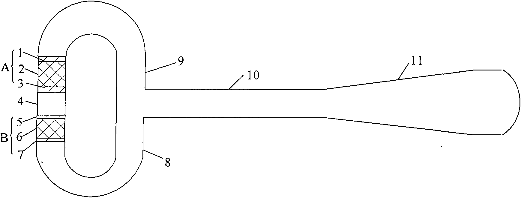
[0048] The structure of this embodiment is as Image 6 As shown, it includes an acoustic power feedback tube 9, a cavity 12, an elastic membrane 13, an engine room temperature cooler 1, an engine thermoacoustic regenerator 2, an engine heater 3, a thermal buffer tube 4, and a refrigerator room temperature. end cooler 5, refrigerating machine thermoacoustic regenerator 6, refrigerating machine cold end heat exchanger 7 and acoustic power recovery pipe 8 form the acoustic wave loop, and the acoustic power feedback pipe 9 and acoustic power feedback pipe 9 in the acoustic wave loop The power recovery pipe 8 is connected to the resonant straight pipe 10 connected at the same time, and the other end of the resonant straight pipe 10 is connected to the resonant cavity 11 to form a resonant branch; wherein the engine room temperature side cooler 1, the engine thermoacoustic regenerator 2 and the engine Thermoacoustic engine A composed of heater 3; thermoacoustic refrigerator B compos...

Embodiment 2

[0052] The structure of this embodiment is as Figure 7 As shown, it includes an acoustic power feedback tube 9, a cavity 12, an elastic membrane 13, an engine room temperature cooler 1, an engine thermoacoustic regenerator 2, an engine heater 3, a thermal buffer tube 4, and a refrigerator room temperature. end cooler 5, refrigerating machine thermoacoustic regenerator 6, refrigerating machine cold end heat exchanger 7 and acoustic power recovery pipe 8 form the acoustic wave loop, and the acoustic power feedback pipe 9 and acoustic power feedback pipe 9 in the acoustic wave loop The power recovery pipe 8 is connected to the resonant straight pipe 10 connected at the same time, and the other end of the resonant straight pipe 10 is connected to the resonant cavity 11 to form a resonant branch; the engine room temperature end cooler 1, the engine thermoacoustic regenerator 2 and the The thermoacoustic engine part A composed of the heater 3; the thermoacoustic refrigerator B comp...

Embodiment 3

[0057] The structure of this embodiment is as Figure 8As shown, it includes an acoustic power feedback tube 9, a capacitive tube 15, an engine room temperature end cooler 1, an engine thermoacoustic regenerator 2, an engine heater 3, a thermal buffer tube 4, a jet pump 16, and a refrigerator connected in sequence. The acoustic wave loop formed by the room temperature end cooler 5, the thermoacoustic regenerator 6 of the refrigerator, the cold end heat exchanger 7 of the refrigerator, and the acoustic power recovery pipe 8, and the acoustic power feedback pipe 9 and the acoustic power feedback pipe 9 in the acoustic wave loop The sound power recovery pipe 8 is connected to the resonant straight pipe 10 connected at the same time, and the other end of the resonant straight pipe 10 is connected to the resonant cavity 11 to form a resonant branch; The thermoacoustic engine A composed of the engine heater 3; the thermoacoustic refrigerator B composed of the room temperature end co...


PUM


Abstract

The invention relates to a thermally-driven thermoacoustic refrigerator device in a traveling and stationary wave type acoustic field, which comprises an acoustic wave circuit consisting of an acoustic power feedback tube, a motor room temperature end cooler, a motor thermoacoustic regenerator, a motor heater, a heat buffer tube, a refrigerator room temperature end cooler, a refrigerator thermoacoustic regenerator, a refrigerator cold end exchanger and an acoustic power recovery tube, and a resonant straight tube communicated with both the acoustic power feedback tube and the acoustic power recovery tube, wherein the acoustic wave circuit and the resonant straight tube are connected sequentially; the other end of the resonant straight tube is communicated with a resonant cavity to form a resonant branch circuit; a thermoacoustic motor and a thermoacoustic refrigerator are positioned in the acoustic wave circuit; and the motor heater of the thermoacoustic motor and the refrigerator room temperature end cooler of the thermoacoustic refrigerator are communicated through the heat buffer tube. In the device, two systems of thermoacoustic conversion are comprehensively used to allow traveling and stationary wave components of acoustic waves to generate a thermoacoustic effect in the motor thermoacoustic regenerator and a pump heating effect in the refrigerator thermoacoustic regenerator; and the acoustic power flow generated by the motor can directly enter the refrigerator for refrigeration, and the structure is simple and compact.

Description

technical field [0001] The invention relates to a refrigerator device, in particular to a heat-driven thermoacoustic refrigerator device of a traveling standing wave sound field. Background technique [0002] The thermoacoustic engine uses the thermoacoustic effect to convert heat energy into sound energy, and the generated sound energy can be used to drive a pulse tube refrigerator or other forms of thermoacoustic refrigerators. The combination of the two is called a thermoacoustic-driven refrigeration system. It has three main advantages: first, the system has no mechanical moving parts, simple structure, low manufacturing cost, and high reliability; second, the working medium is an environmentally friendly gas; third, the system directly uses thermal energy as the driving source, and is expected to It is applied to occasions where thermal energy resources are abundant but electricity is scarce, especially in remote areas and offshore oilfield natural gas liquefaction, etc...

Claims


Application Information

Patent Timeline
Patent Type & Authority Applications(China)
IPC IPC(8): F25B23/00
Inventor 李青康慧芳胡忠军周刚
Owner TECHNICAL INST OF PHYSICS & CHEMISTRY - CHINESE ACAD OF SCI
Why Eureka
Try Eureka