Process for producing slush nitrogen and apparatus therefor

A nitrogen slurry, liquid nitrogen technology, applied in the usage of superconductor elements, nitrogen purification/separation, heat storage equipment, etc., can solve the problems of increasing cooling temperature and performance limitations of superconducting devices

Inactive Publication Date: 2006-03-01
MAYEKAWA MFG CO LTD
View PDF6 Cites 12 Cited by
  • Summary
  • Abstract
  • Description
  • Claims
  • Application Information

AI Technical Summary

Problems solved by technology

If the cooling temperature is raised to about the boiling point using this method, the performance of the superconducting device is limited to this temperature

Method used


Image

  • Process for producing slush nitrogen and apparatus therefor
  • Process for producing slush nitrogen and apparatus therefor
  • Process for producing slush nitrogen and apparatus therefor

Examples


no. 1 approach

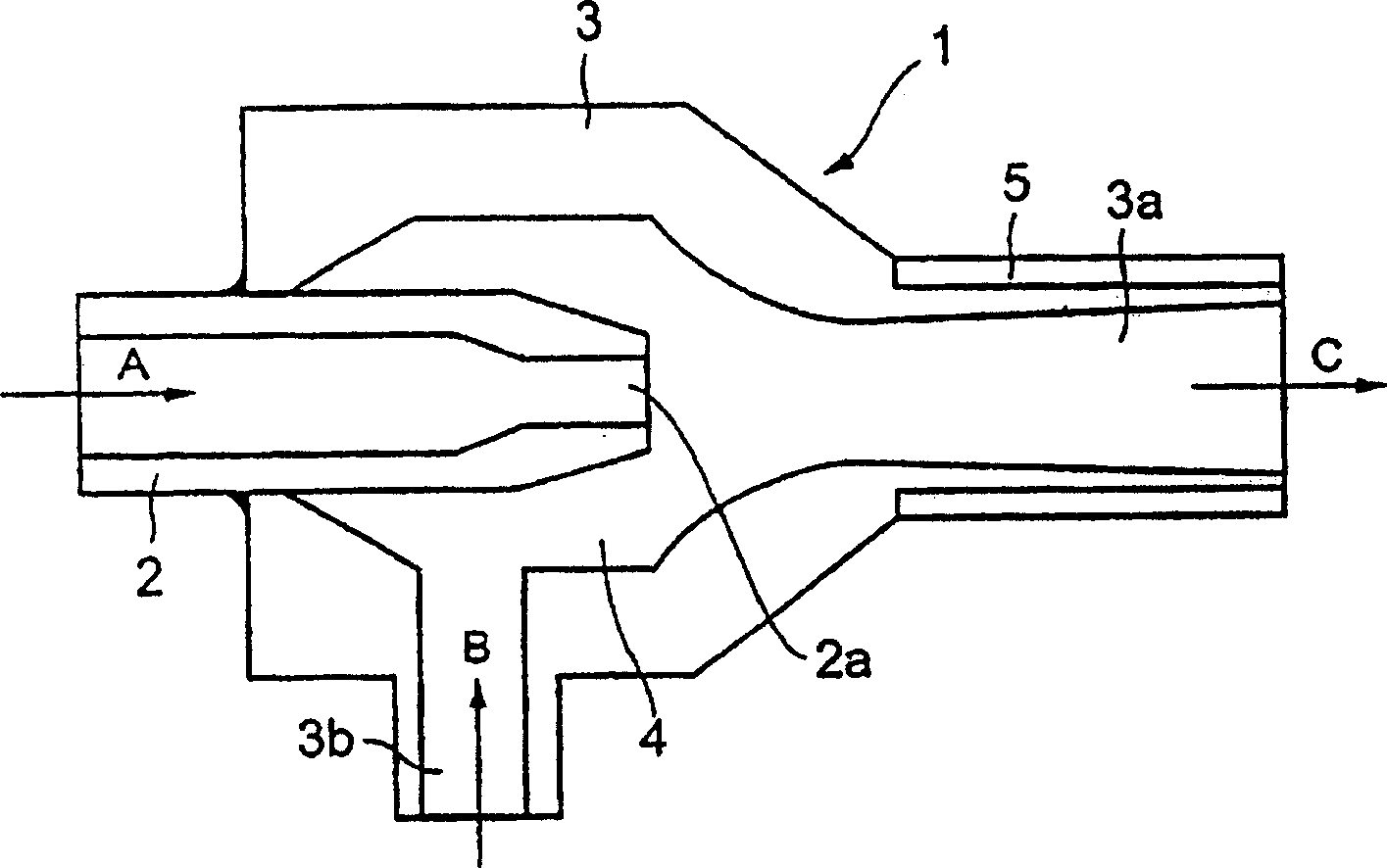
[0075] figure 1 is a cross-sectional view of an injector arranged in a cryogenic vessel. Such as figure 1 As shown, injector 1 comprises a nozzle 2 and an outer cylinder 3 having a diffuser portion 3a. The nozzle 2 protrudes into the interior space 4 of the outer cylinder 3 . Liquid or gas coolant is supplied as indicated by arrow A, and is blown from the nozzle opening 2a toward the diffuser portion 3a. As indicated by arrow B, liquid nitrogen contained in the cryogenic container is sucked into the inner space 4 from the suction hole 3b of the outer cylinder 3, and is blown into the inner space of the cryogenic container together with the coolant flowing through the diffuser portion 3a. A heater 5 is provided outside the diffuser portion 3a to prevent solid nitrogen from solidifying and being fixed thereto.

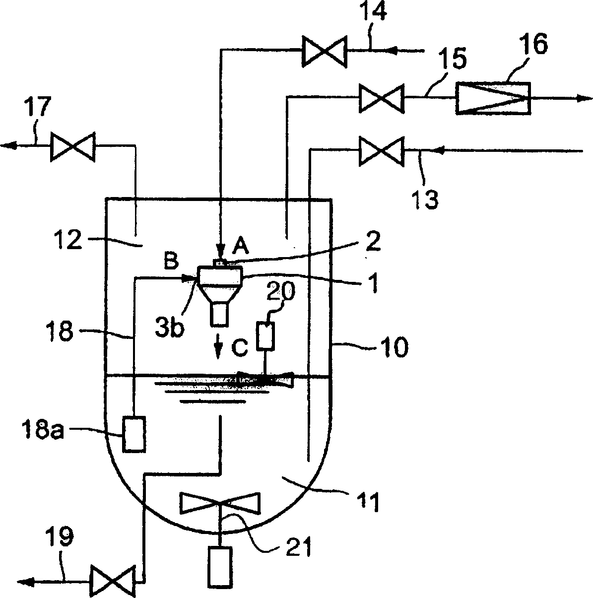
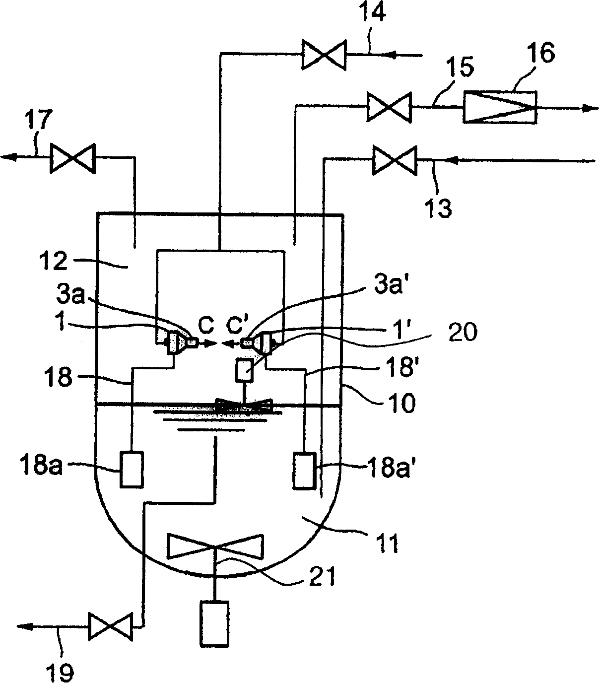
[0076] figure 2 It is a figure showing the piping of the cryogenic container provided with an ejector. image 3 It is a figure which shows the case where two inje...

no. 2 approach

[0087] Figure 5 is a schematic diagram of the apparatus of the second embodiment of the present invention. exist Figure 5 Among them, 104 is a heat-insulated container; 102 is liquid nitrogen contained in the container; 109 is a vacuum pump (decompression device) for decompressing gaseous substances; 108 is a thermometer (temperature measuring device) capable of detecting triple point ; 107 is a level instrument that can measure the current volume value; 103 is a stirring blade (for stirring the liquid surface part) that can break solid nitrogen blocks solidified on the liquid surface; 105 is the bottom that can further crush the solid nitrogen that settles Stirring blade (a device used to stir the bottom).

[0088] Liquid nitrogen 102 is stored in a thermally insulated container 104, and a vacuum pump 109 is used to depressurize the gas phase inside the container. When the decompression is performed, the liquid nitrogen evaporates and the temperature of the liquid nitrog...

no. 3 approach

[0092] Next, an embodiment of estimating the nitrogen slurry concentration is described. The latent heat of evaporation of nitrogen, latent heat of solidification, liquid nitrogen density, solid nitrogen density, volume of nitrogen at the triple point, volume of nitrogen after nitrogen slurry is generated, liquid nitrogen corresponding value of evaporated nitrogen volume, volume of evaporated solid nitrogen, The heat entering the heat-insulated container and the time consumed to generate nitrogen slurry are denoted as H v (kJ / kg), H s (kJ / kg), M l (kg / m 3 ), M s (kg / m 3 ), V s (m 3 ), V f (m 3 ), X v (m 3 ), X s (m 3 ), Q(kW) and T(s).

[0093] According to the law of conservation of energy,

[0094] h v × M l ×X v =H s × M s ×X s +Q×T (1)

[0095] By the law of conservation of mass,

[0096] V s × M l =(V f -X s )×M l +X s × M s +X v × M l (2).

[0097] Xv and Xs are obtained from the above simultaneous equations, an...


PUM

PropertyMeasurementUnit
densityaaaaaaaaaa

Abstract

A process for producing slush nitrogen, comprising charging a low-temperature container with liquid nitrogen and arranging an ejector capable of drawing out liquid nitrogen by suction by spewing a refrigerant liquid or gas, such as low-temperature helium gas or liquid helium of pressure higher than in the space within the container, into the container so that the liquid nitrogen drawn out by suction by the refrigerant and spewed together with the refrigerant is refrigerated by the refrigerant, becomes particulate solid nitrogen and falls, while discharging the gas lying in the space within the container outside the container so as to constantly maintain the space at atmospheric pressure or higher. Further, there is provided a method of refrigerating a superconductive object including a substance exhibiting a superconductive state at temperatures close to the temperature of liquid nitrogen or close to the temperature at which the liquid nitrogen and the solid nitrogen coexist, characterized in that the object is immersed in slush nitrogen held in an adiabatic container so as to effect contact of the object with slush nitrogen and refrigeration thereof.

Description

technical field [0001] The present invention relates to a method and apparatus for producing a slurry (i.e., slushnitrogen) of a mixture of liquid nitrogen and solid nitrogen, a method for estimating the solids concentration of the nitrogen slurry, and a method for cooling the nitrogen slurry . Background technique [0002] Liquid nitrogen is widely used as a coolant. When a jelly-like mixture of solid nitrogen and liquid nitrogen is used, its density and cooling capacity per unit mass increase, making the mixture an effective coolant. However, no method has been established for economically producing a nitrogen slurry containing solid nitrogen having a uniform and fine particle size. [0003] Compared with liquid nitrogen, nitrogen slurry has an excellent ability to absorb heat loads because the latent heat of fusion of solid nitrogen is used, so nitrogen slurry can be effectively used for cooling power transmission cables for high-temperature superconductivity and high-t...

Claims


Application Information

Patent Timeline
Patent Type & Authority Applications(China)
IPC IPC(8): C01B21/04F28D20/00H01B12/16G01N7/00
CPCY02E60/321Y02E70/30Y02E40/64Y02E60/142Y02E40/647Y02E40/60Y02E60/14
Inventor 川村邦明町田明登池内正充服部一裕松尾幸一柳秀治
Owner MAYEKAWA MFG CO LTD
Why Eureka
Try Eureka