System and method for producing and delivering vapor

a technology of vapor delivery system and vapor production method, which is applied in the direction of steam generation using steam absorption, lighting and heating apparatus, heating types, etc. it can solve the problems of inability to produce less than desirable byproducts, inability to control the operation conditions of the system, and many drawbacks of the type of system, so as to achieve quick and efficient operation, improve the effect of controllability and controllability

Active Publication Date: 2010-03-16
ENTEGRIS INC +1
View PDF29 Cites 22 Cited by
  • Summary
  • Abstract
  • Description
  • Claims
  • Application Information

AI Technical Summary

Benefits of technology

[0018]Reduced size may be another advantage of the present invention. Embodiments of the present invention may provide vapor delivery systems which are 11.25 inches×5.5 inches×8.5 inches, 10 inches×5 inches×9 inches, or smaller.
[0019]Embodiments of the present invention may provide an advantage of allowing portions of the vapor delivery system to achieve a set of conditions both more quickly and more efficiently and may allow a finer granularity of control over these operating conditions. For example, heaters may be controlled to within + / −2° C. of a setpoint.
[0020]Other embodiments of the present invention provide the technical advantage of a consistent vapor saturation and vapor delivery while operating at sub-atmospheric conditions for better safety. In some embodiments, these advantages may, in part, be achieved by utilizing components that are less affected by the operating conditions of the system, for example a thermal based mass flow controller.
[0021]Embodiments of the present invention may also be able to continue delivery of vapor in the event of a temporary interruption to a liquid source by utilizing the liquid remaining in a vaporizer tank.
[0022]Additionally, embodiments of the present invention may provide the advantage that pressure within the vapor tank does not have to be lowered for vapor production or delivery to occur.
[0023]Certain embodiments of the invention may further have the ability to communicate with external devices and provide valuable data which can be recorded and analyzed. This data may include, but is not limited to, flow, temperature, valve status, etc.

Problems solved by technology

Moreover, the use of many of these photochemicals may result in the production of less than desirable byproducts.
This type of system has many drawbacks, however.
First and foremost, because the vaporization chamber of these types of systems must be maintained at a relatively high temperature these types of systems are relatively inefficient.
Part and parcel with this problem, is the problem of condensation.
Not only does this requirement entail higher energy consumption for such systems, but additionally, these higher temperatures may affect the reliability and stability of system components while making the use of such systems hazardous to technicians or other operators.
The use of these high temperatures has other adverse effects as well.
By vaporizing the liquid at a higher temperature contaminants within the liquid are more likely to be vaporized, resulting in potential corrosion along the flow path of the vapor, or contamination of the process itself.
Additionally, as the flow controllers used to regulate the delivery of vapor may be pressure based mass flow controllers (MFCs), the high temperature used in these systems may cause these pressure based MFCs to drift, affecting the precision with which these systems can regulate the flow of vapor.
These systems suffer from a number of failings as well.
The majority of these shortcomings pertain to the inability of these systems to deliver either a high flow rate of vapor or to deliver vapor over long periods of time.
As the reaction utilized to produce vapor in these systems is severely exothermic air-cooling is usually required, making these systems prohibitively expensive for most uses.
Additionally, these systems suffer from some of the same problems discussed above.
Namely, variation in the reaction used to create water vapor may result in variable flow rates while a single ongoing reaction may not produce the desired flow rate of water vapor.

Method used


Image

  • System and method for producing and delivering vapor
  • System and method for producing and delivering vapor
  • System and method for producing and delivering vapor

Examples


Embodiment Construction

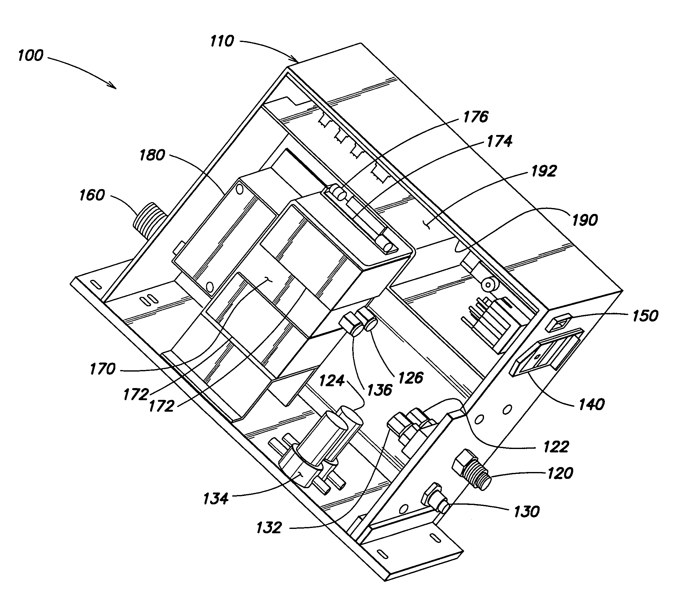
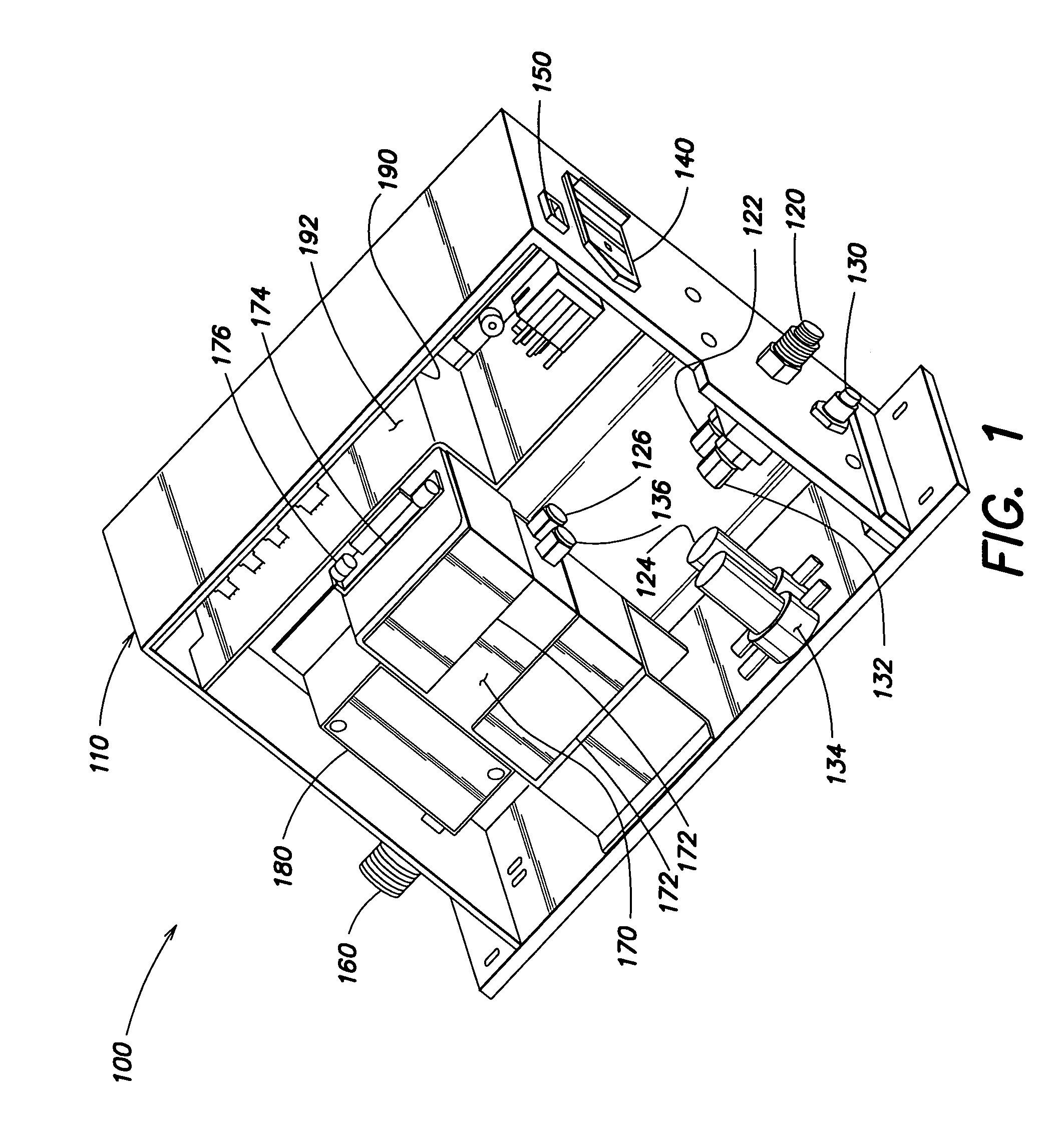
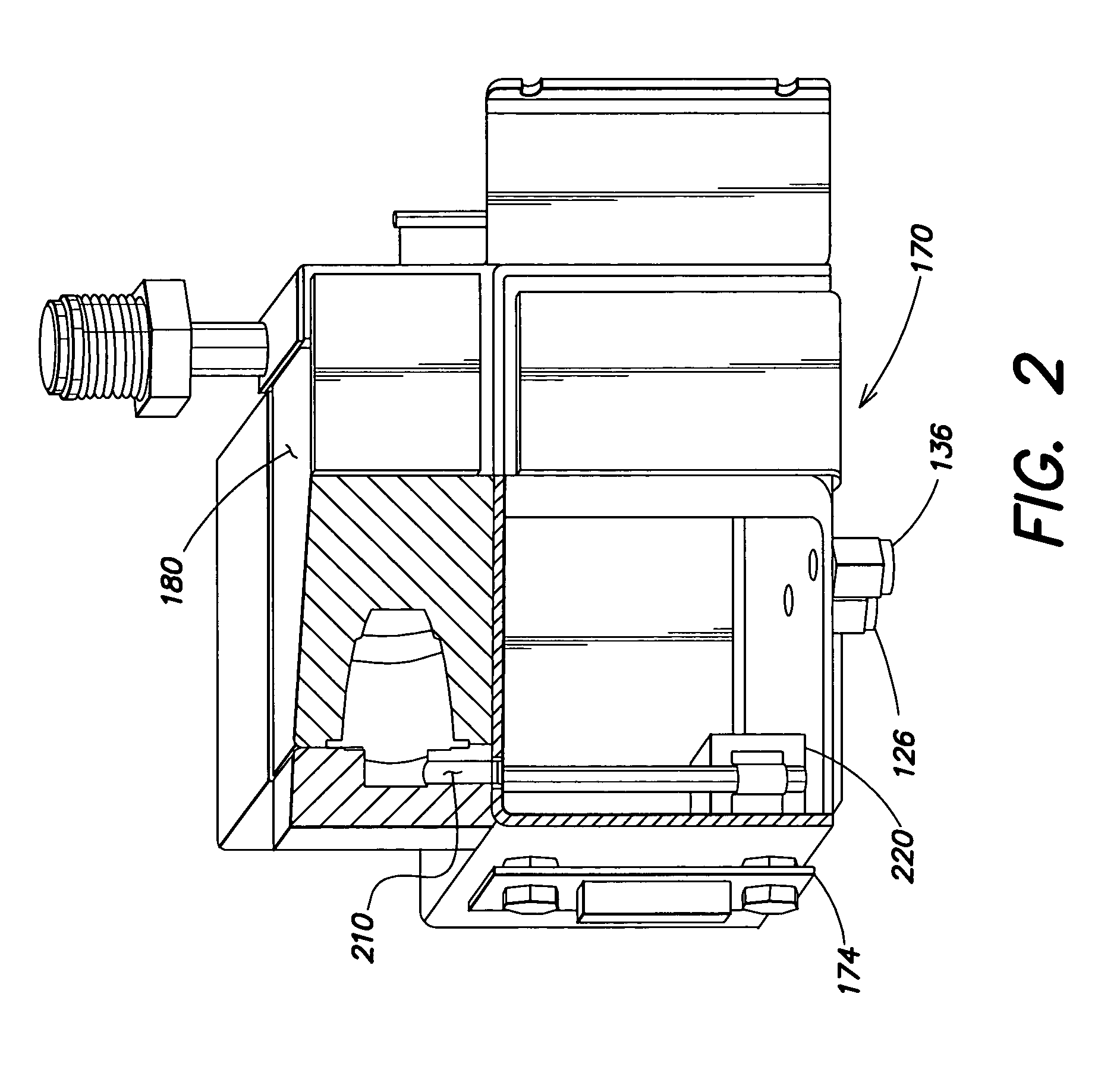
[0043]The invention and the various features and advantageous details thereof are explained more fully with reference to the nonlimiting embodiments that are illustrated in the accompanying drawings and detailed in the following description. Descriptions of well known starting materials, processing techniques, components and equipment are omitted so as not to unnecessarily obscure the invention in detail. It should be understood, however, that the detailed description and the specific examples, while indicating preferred embodiments of the invention, are given by way of illustration only and not by way of limitation. Various substitutions, modifications, additions and / or rearrangements within the spirit and / or scope of the underlying inventive concept will become apparent to those skilled in the art from this disclosure.

[0044]Before explaining embodiments of the present invention it should be noted that though the specific embodiments of the present invention described herein have b...


PUM

PropertyMeasurementUnit
pressureaaaaaaaaaa
operating temperatureaaaaaaaaaa

Abstract

Systems and methods for producing and delivering vapor are disclosed. A vaporizer tank containing a liquid may be heated such that liquid within the tank is heated and vapor generated. The flow of this vapor to a destination may then be regulated. Embodiments of the present invention may control the temperature of this liquid such that a saturated vapor condition is substantially maintained in the vaporizer tank. The vaporizer tank is coupled to a mass flow controller which regulates the delivery of the vapor to downstream components. By substantially maintaining the saturated vapor condition within the vaporizer tank the pressure of vapor at the mass flow controller can be substantially maintained and a stable and consistent flow rate of vapor achieved.

Description

TECHNICAL FIELD OF THE INVENTION[0001]This invention relates generally to vapor delivery systems. More particularly, embodiments of the present invention relate to efficient vapor delivery systems. Even more particularly, embodiments of the present invention relate to stable, high-flow rate vapor delivery systems operating at sub-atmospheric conditions.BACKGROUND OF THE INVENTION[0002]There are many applications for which delivery of vapor of different types of liquids is desired. In semiconductor processing, for example, it may be desired to deliver photochemicals, such as photoresist chemicals, in vapor form to a process chamber to control the amount and rate at which these photochemicals are applied to a semiconductor wafer. Moreover, the use of many of these photochemicals may result in the production of less than desirable byproducts. To deal with these harmful byproducts and clean a process chamber of these byproducts or other chemicals before another processing stage, water v...

Claims


Application Information

Patent Timeline
Patent Type & Authority Patents(United States)
IPC IPC(8): A01G13/06
CPCF22B35/00F22B35/005
Inventor BUCHANAN, DARYLTARIQ, FAISALMEI, HAITISON, STUART
Owner ENTEGRIS INC
Why Eureka
Try Eureka