Plotter as well as plotting method and using method thereof
The technology of a plotter and a drawing pen, which is applied in the field of plotters, can solve the problems of not being able to carry it around, the specification of drawing paper is small, and cannot be used, and achieve the effects of being easy to carry around, drawing fast, and saving power
- Summary
- Abstract
- Description
- Claims
- Application Information
AI Technical Summary
Problems solved by technology
Method used
Image
Examples
no. 1 example
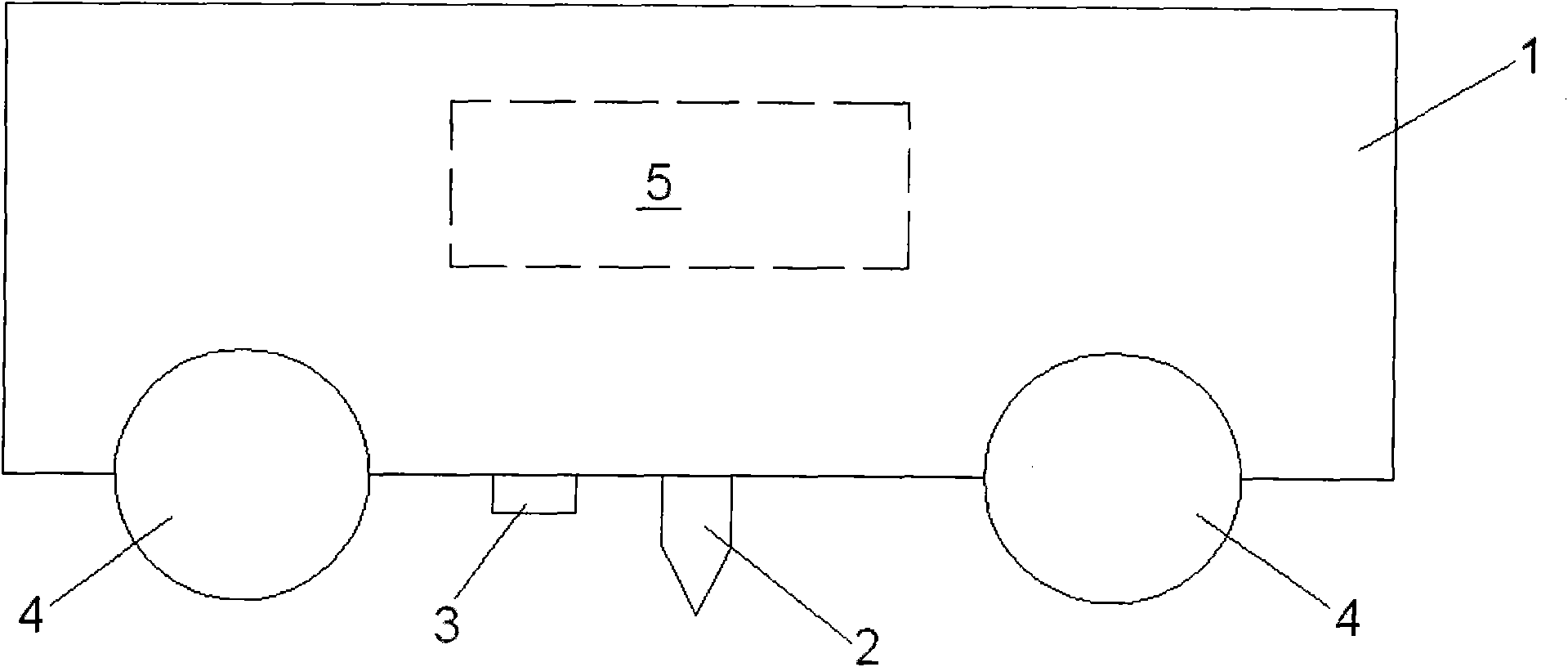
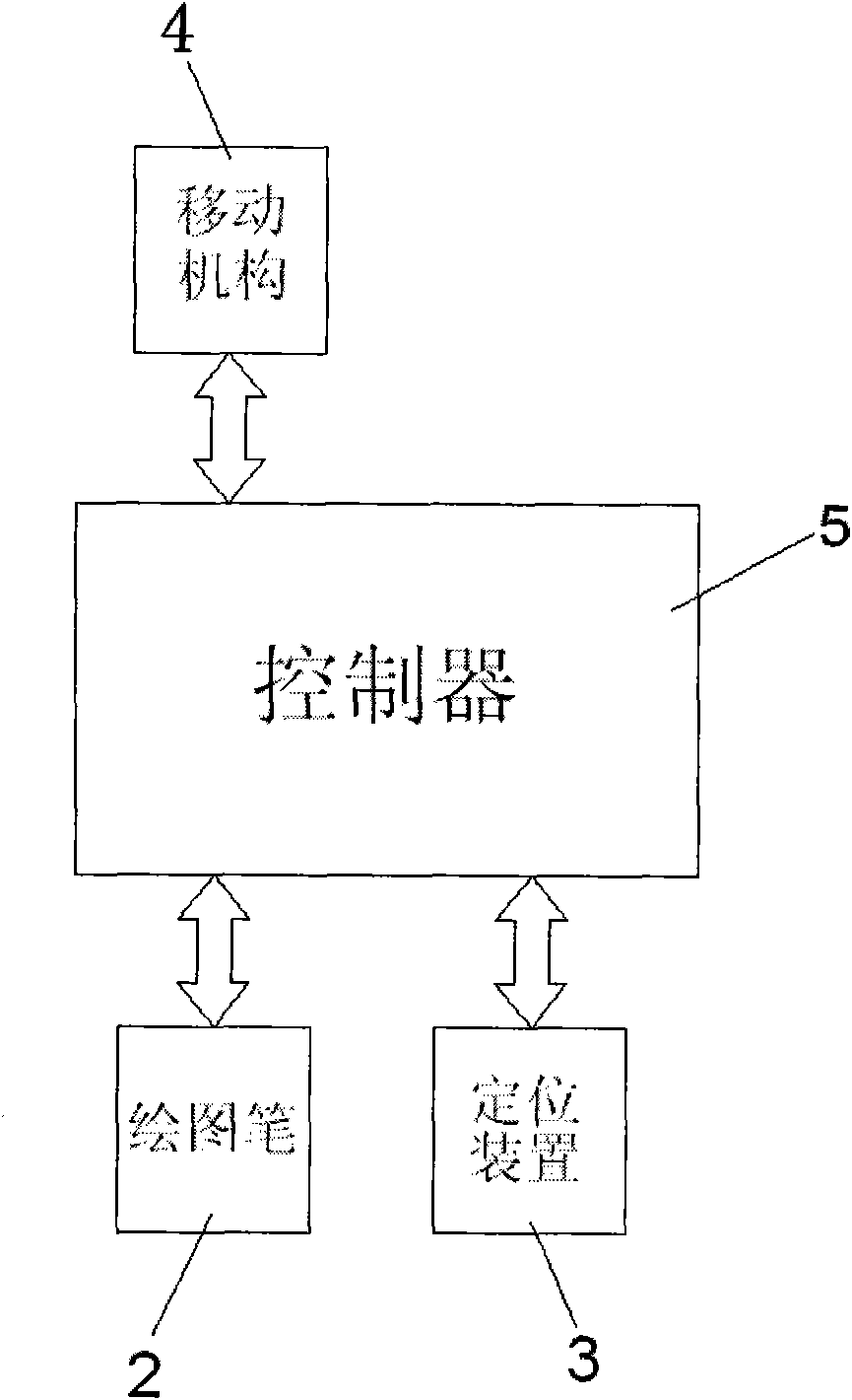
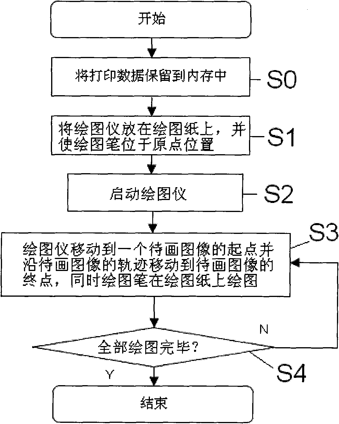
[0038] Figure 1 to Figure 6 An exemplary first embodiment of the plotter of the present invention is shown. specifically, figure 1 Show the structural representation of the first embodiment of the plotter of the present invention; figure 2 show figure 1 The control schematic diagram of the plotter shown; image 3 show figure 1 The drawing method of the plotter shown; Figure 4 show figure 1 A schematic diagram of the method of use or the process of using the plotter shown; Figure 5 Schematic showing the use of two independent optical position sensors to detect the position of the drawing pen relative to the origin; Figure 6 show Figure 5 Schematic diagram of the operation of the optical position sensor shown.
[0039] Such as figure 1 As shown, in this embodiment, the plotter includes a main body 1 , a plotting pen 2 , a positioning device 3 , a moving mechanism 4 and a controller 5 .
[0040] Specifically, in this embodiment, as figure 1 As shown, the control...
no. 2 example
[0072] Figure 7 A second embodiment of the plotter of the present invention is shown, which employs an optical position sensor 311 and an angle sensor 312 to detect the position of the drawing pen relative to the origin.
[0073] Such as Figure 7 As shown, the difference between the plotter shown in the second embodiment of the present invention and the plotter shown in the first embodiment is only that the positioning device of the plotter in the second embodiment consists of an optical position sensor 311 and an angle sensor 312 instead of two optical position sensors.
[0074] exist Figure 7 In , the dashed line represents the plotter without rotation, and the solid line represents the plotter after rotation.
[0075] In this example, if Figure 7 As shown, the optical position sensor 311 can obtain the current position (XS1, YS1) of the optical position sensor 311 relative to the origin in real time, and the angle sensor 312 can obtain the rotation angle α of the pl...
PUM
 Abstract
Description
Claims
Application Information
 - R&D
- Intellectual Property
- Life Sciences
- Materials
- Tech Scout
- Unparalleled Data Quality
- Higher Quality Content
- 60% Fewer Hallucinations
Browse by: Latest US Patents, China's latest patents, Technical Efficacy Thesaurus, Application Domain, Technology Topic, Popular Technical Reports.
© 2025 PatSnap. All rights reserved.Legal|Privacy policy|Modern Slavery Act Transparency Statement|Sitemap|About US| Contact US: help@patsnap.com


