

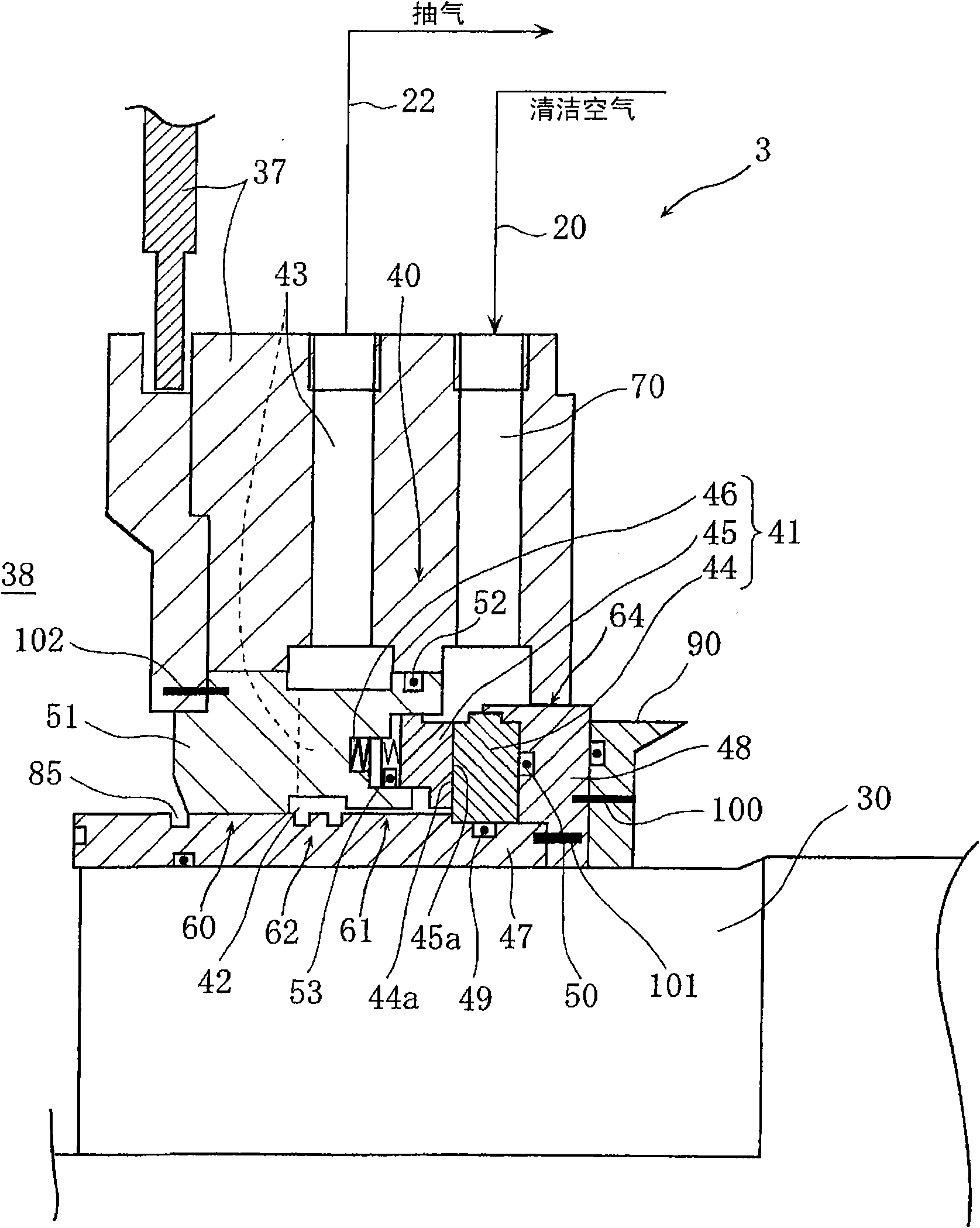
A shaft sealing structure of a steam compressor in a vacuum concentration device
A steam compressor and vacuum concentration technology, which is applied to the sealing of the engine, mechanical equipment, engine components, etc., can solve problems such as adverse effects on heat transfer performance, and achieve the effect that the heat transfer performance will not deteriorate
- Summary
- Abstract
- Description
- Claims
- Application Information
AI Technical Summary
Problems solved by technology
Method used
Image

Examples
Embodiment Construction
[0027] Hereinafter, the present invention will be described in detail based on embodiments. In addition, this invention is not limited to the following embodiment.
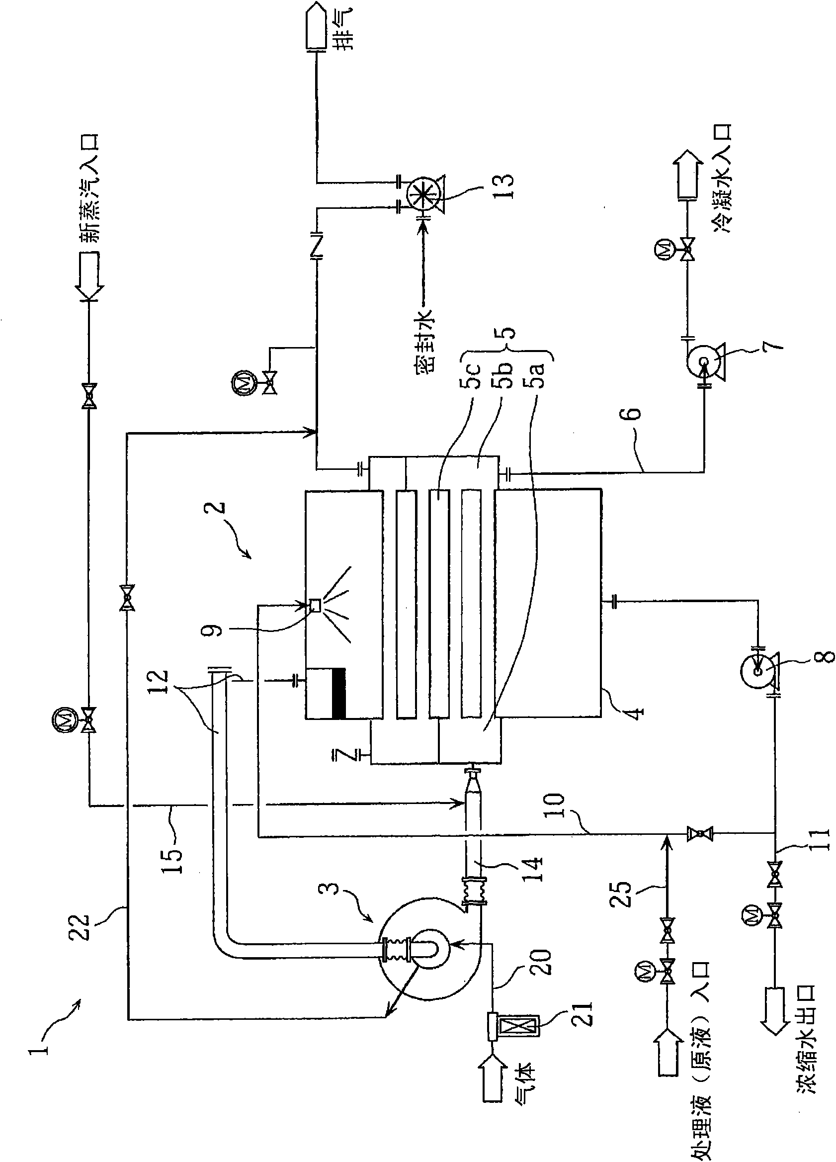
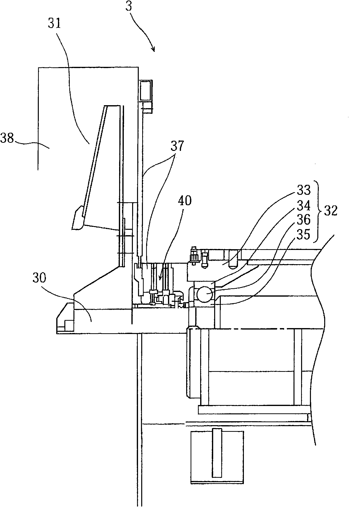
[0028] figure 1 It is an overall configuration diagram of a vacuum concentration facility equipped with a vapor compressor according to an embodiment. The vacuum concentrator 1 is provided with a horizontal tube evaporator 2 for evaporating the supplied treatment liquid, and a steam compressor 3 for adiabatically compressing and generating fresh steam, and is configured to use the steam compressor 3 to increase the temperature and pressure The steam returns to the horizontal tube evaporator 2 as a heat source for evaporating the treatment liquid.
[0029] The horizontal tube evaporator 2 includes an evaporation tank 4 formed in a cylindrical shape and capable of storing a treatment liquid inside. A heater 5 composed of a pair of left and right headers 5a, 5b and a plurality of horizontal heat transfer tubes 5c ...
PUM
 Abstract
Description
Claims
Application Information