High-pressure hydrolysis self-circulating device for oil

A self-circulating, high-pressure technology, applied in the field of self-circulating devices for high-pressure hydrolysis of grease, can solve the problems of low safety factor, time-consuming and electricity-consuming

Inactive Publication Date: 2011-04-06
杨玉赞
View PDF4 Cites 2 Cited by
  • Summary
  • Abstract
  • Description
  • Claims
  • Application Information

AI Technical Summary

Problems solved by technology

[0003] At present, most of the oil hydrolysis equipment widely used in China adopts power circulation and stirring in the hydrolysis process, whi

Method used


Image

  • High-pressure hydrolysis self-circulating device for oil
  • High-pressure hydrolysis self-circulating device for oil

Examples


Embodiment Construction

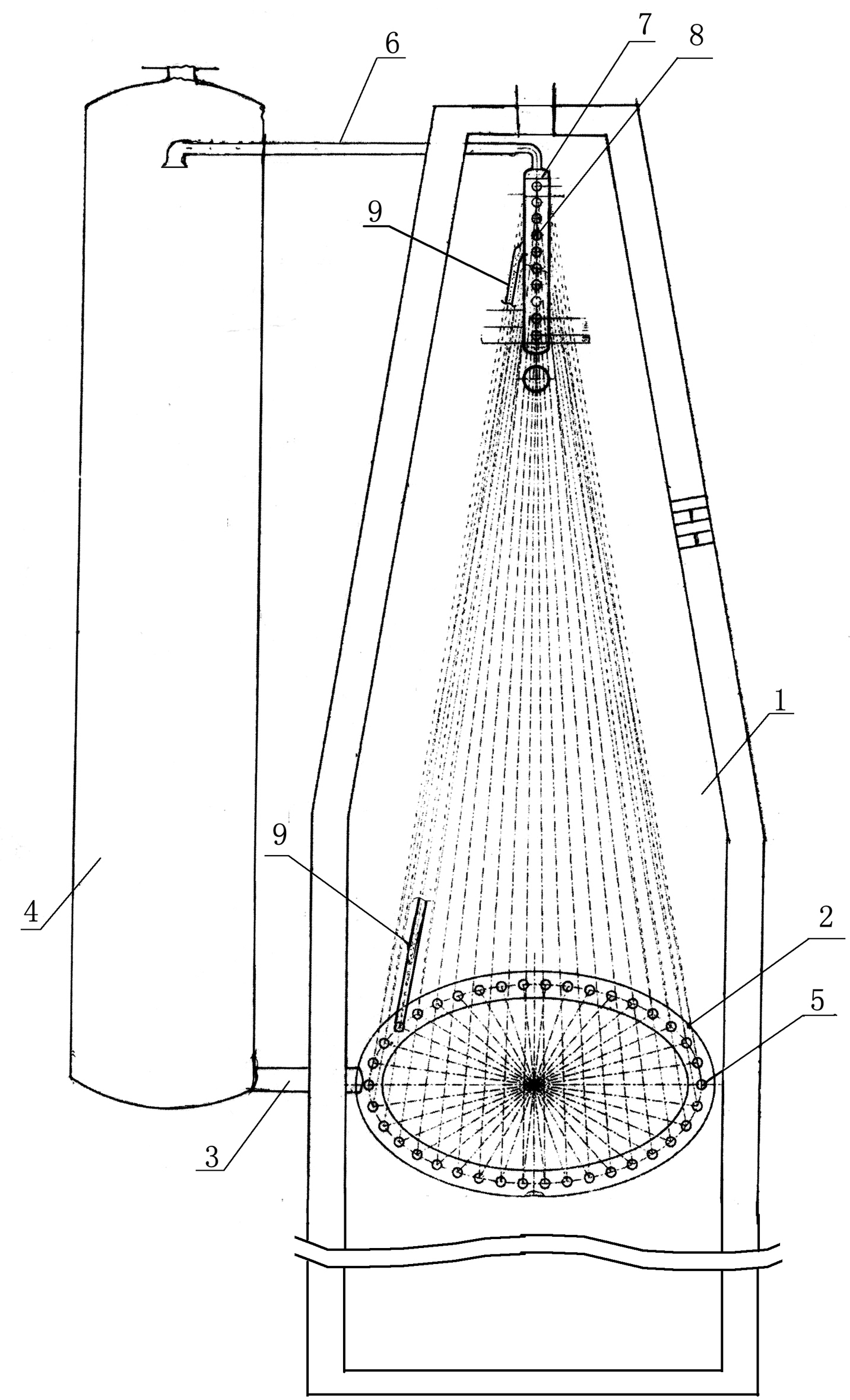
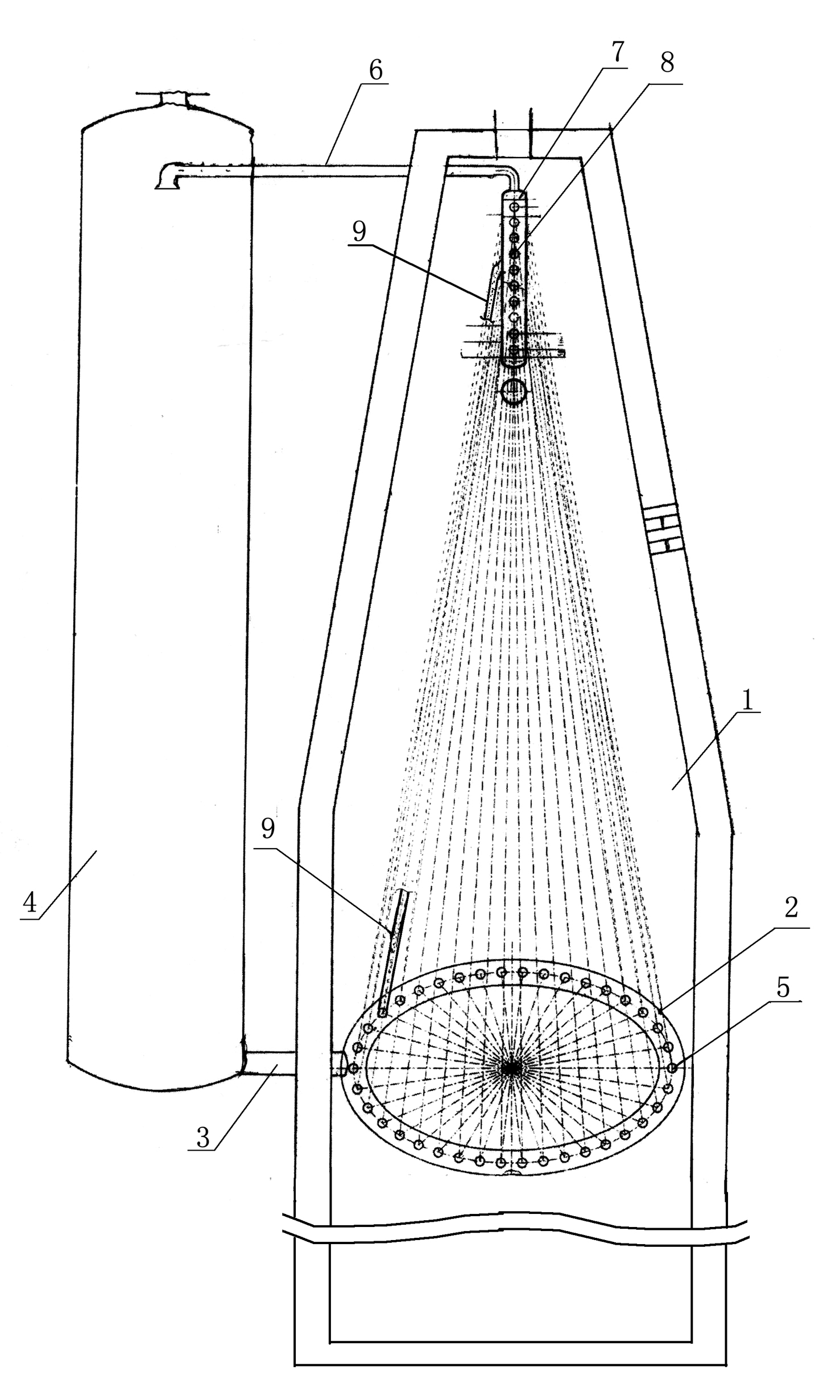
[0011] As shown in the drawings, the present invention includes a heating furnace body 1, a chassis tube 2 arranged in the heating furnace body 1 through a feed pipe 3 and a lower end of the hydrolysis tower 4, and more than 10 evenly arranged on the chassis tube 2 discharge hole 5, the vertical pipe 7 that is arranged on the upper end of the heating furnace body 1 through the discharge pipe 6 and the upper end of the hydrolysis tower 4, and more than 10 feed holes 8 that are evenly arranged on the vertical pipe 7. More than 10 vertical tubes 9 are uniformly distributed and connected to the feed holes 8 on the vertical tubes 7 and the discharge holes 5 of the chassis tubes 2 . Through the feed pipe 3, the medium mixed with oil and water in a weight ratio of 1:1 is sent into the heating chassis pipe 2, the vertical pipe 9 and the vertical pipe 7, and then heated through the vertical pipe 9 and the discharge pipe 6 Entering the hydrolysis tower 4, the main principle of the heat ...


PUM


Abstract

The invention relates to a high-pressure hydrolysis self-circulating device for oil, comprising a heating furnace, a bottom coil arranged in the heating furnace and communicated with the lower end of a hydrolysis tower through a feeding pipe, more than 10 discharging holes evenly arranged on the bottom coil, a standpipe arranged at the upper end in the heating furnace and communicated with the upper end of the hydrolysis tower through a discharging pipe, more than 10 feeding holes evenly arranged on the standpipe, and more than 10 vertical pipes distributed evenly and communicated with the feeding holes on the standpipe and the discharging holes on the bottom coil. The high-pressure hydrolysis self-circulating device for oil can automatically complete circulation, save electricity and energy without the phenomena such as escaping, bursting, dripping and leakage and has high safety factor.

Description

[0001] technical field [0002] The invention relates to a high-pressure hydrolysis self-circulation device for grease. Background technique [0003] At present, most of the oil hydrolysis equipment widely used in China adopts power circulation and stirring during the hydrolysis process, which not only consumes time and electricity in the operation process, but also sometimes runs, pops, drips, and leaks, and has a low safety factor. Contents of the invention [0004] The technical problem to be solved by the present invention is to provide a high-pressure hydrolysis self-circulation device for grease that can automatically complete the circulation and save electricity and energy. [0005] The present invention adopts following technical scheme: [0006] The invention includes a heating furnace body, a chassis tube arranged in the heating furnace body through a feed pipe connected to the lower end of the hydrolysis tower, more than 10 discharge holes uniformly arranged on...

Claims


Application Information

Patent Timeline
IPC IPC(8): B01J4/00C11C1/04
Inventor 杨玉赞曹景欣杨淑健李立仙李立孔徐朝霞李立秀
Owner 杨玉赞
Why Eureka
Try Eureka