Steam generating device for high-power solar-thermal power station

A steam generating device and technology of photothermal power plants, applied in steam generation, steam generation methods, steam generation methods using solar energy, etc., can solve the problems of low steam quality, difficult manufacturing, high cost, etc., to improve reliability and cost Low, simple structure effect

Pending Publication Date: 2020-10-16
中国船舶重工集团公司第七0三研究所
View PDF1 Cites 0 Cited by
  • Summary
  • Abstract
  • Description
  • Claims
  • Application Information

AI Technical Summary

Problems solved by technology

[0004] The purpose of the present invention is to solve the problems of difficulty in manufacturing, high cost and low steam quality in existing high-power heat exchange power stations using traditional kettle-type reboilers, and to provide a steam generator for high-power solar-thermal power stations. device

Method used


Image

  • Steam generating device for high-power solar-thermal power station
  • Steam generating device for high-power solar-thermal power station
  • Steam generating device for high-power solar-thermal power station

Examples


specific Embodiment approach 1

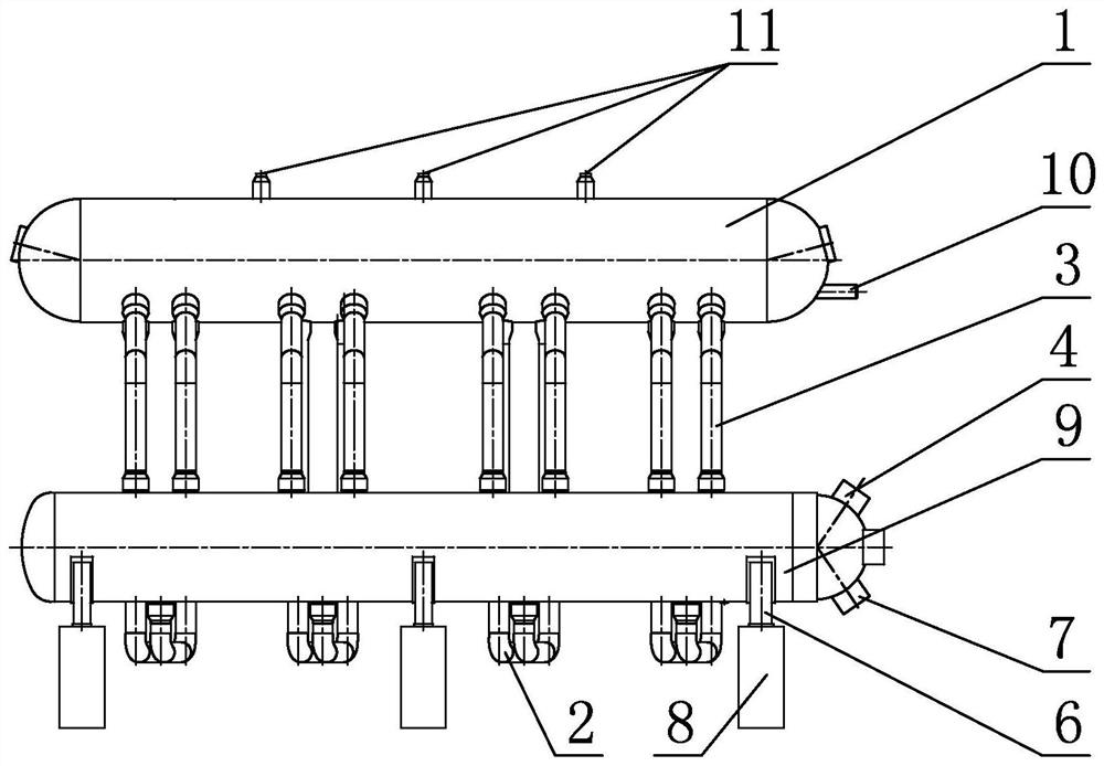
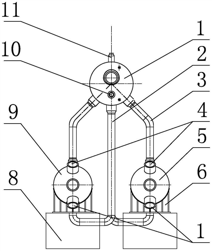
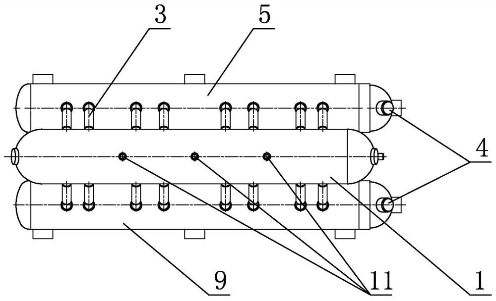
[0020] Specific implementation mode one: combine figure 1 Describe this embodiment mode, a kind of steam generation device for high-power photothermal power station of this embodiment mode, it comprises steam drum 1, evaporator A5, evaporator B9, several descending pipes 2 and several ascending pipes 3, evaporator A5 and The evaporator B9 is arranged in parallel in the horizontal direction, and the steam drum 1 is arranged in parallel above the evaporator A5 and the evaporator B9 in the horizontal direction, and the upper part of one end of the evaporator A5 and the evaporator B9 is respectively provided with a tube-side inlet 4, and the evaporator A5 and the evaporator The lower part of one end of the device B9 is respectively provided with a tube-side outlet 7, and one end of the steam drum 1 is provided with a water supply inlet 10, and the water supply inlet 10 communicates with the water storage area of ​​the steam drum 1, and the upper part of the steam drum 1 is along th...

specific Embodiment approach 2

[0021] Specific implementation mode two: combination figure 1 Describe this embodiment, the evaporator A5 of this embodiment communicates with the water storage area inside the steam drum 1 through four downcomers 2, and the evaporator B9 communicates with the water storage area inside the steam drum 1 through four downcomers 2. Other compositions and connections are the same as in the first embodiment.

specific Embodiment approach 3

[0022] Specific implementation mode three: combination figure 1 To illustrate this embodiment, the bottom of the evaporator A5 of this embodiment communicates with the steam-water separation area inside the steam drum 1 through four rising pipes 3, and the bottom of the evaporator B9 communicates with the steam-water separation area inside the steam drum 1 through four rising pipes 3 . Other compositions and connections are the same as those in Embodiment 1 or Embodiment 2.


PUM


Abstract

The invention discloses a steam generating device for a high-power solar-thermal power station, and relates to the field of electric power and chemical engineering systems. The device solves the problems that traditional kettle-type reboilers used by existing high-power heat exchange power stations are difficult to manufacture with high cost and low steam quality. A steam drum of the device is horizontally mounted above an evaporator A and an evaporator B in a parallel mode. One end of the steam drum is provided with a feed-water inlet, and the feed-water inlet is communicated with a water storage area of the steam drum. The upper part of the steam drum is provided with a plurality of steam outlets along the axis of the steam drum. The water storage area inside the steam drum is respectively communicated with the upper parts of the evaporator A and the evaporator B through a plurality of downward pipes. The bottoms of the evaporator A and the evaporator B are respectively communicatedwith a steam-water separation area inside the steam drum through a plurality of upward pipes. Air outlets formed on the steam-water separation area are communicated with the steam outlets formed on the steam drum. Water outlets formed on the steam-water separation area are communicated with the water storage area inside the steam drum. The device is used for realizing natural steam circulation under a non-heated state of the upward pipes.

Description

technical field [0001] The invention relates to the field of electric power and chemical industry systems, in particular to a steam generating device for a high-power photothermal power station. Background technique [0002] Energy and environmental issues are two important issues facing the world today. In recent years, my country has always attached great importance to the development and utilization of new energy sources. Among them, the use of solar power generation is an effective way to alleviate or even solve energy problems. Countries around the world are also actively doing s hard work. The solar-thermal power generation steam generation system is an important heat exchange equipment, and the steam generation device is a main component of the equipment. Its function is to convert the nearly saturated water heated by the preheater into saturated steam through heat exchange. The solar-thermal power station mainly adopts a kettle-type reboiler, but if a kettle-type reb...

Claims


Application Information

Patent Timeline
Patent Type & Authority Applications(China)
IPC IPC(8): F22B1/00F22B37/22F22B37/14F22B37/10
CPCF22B1/006F22B37/104F22B37/141F22B37/221
Inventor 李鑫陈玉翔徐慧强韩嘉栋王景富
Owner 中国船舶重工集团公司第七0三研究所
Why Eureka
Try Eureka