Thrust rudder

A technology of thrust and sub-rudder, which is applied in directions such as rudder steering and steering, which can solve problems such as affecting rudder efficiency, insufficient, and not taking into account, and achieve the effects of improving propulsion efficiency, increasing maximum speed, and improving maneuverability

Inactive Publication Date: 2013-06-05
HARBIN ENG UNIV
View PDF13 Cites 0 Cited by
  • Summary
  • Abstract
  • Description
  • Claims
  • Application Information

AI Technical Summary

Problems solved by technology

At present, the rudders commonly used on ships do not make full use of the beneficial interference of propeller rudders, because the magnitude and direction of the induced velocities produced by propellers at different rudder heights are different, and conventional rudders are not considered in the design to this point
Therefore, someone proposed the scheme of twisting the rudder, which is to deflect the section of the rudder at different heights by an angle according to the direction of incoming flow, so that it can more fully cooperate with the wake field behind the propeller, make full use of the energy of the propeller wake, and adjust the shape of the rudder. Control it so that the resistance is as small as possible when the rudder angle is not turned, but it will affect the rudder effect when the rudder angle is turned, which will be detrimental to the maneuverability of the ship
The flap rudder divides the rudder blades into two main parts and flaps that rotate according to a certain rule. When the flaps are deflected, it is equivalent to increasing the camber of the rudder section, which can effectively improve the rudder effect and the maneuverability of the ship. Beneficial, but unable to save energy

Method used


Image

  • Thrust rudder
  • Thrust rudder
  • Thrust rudder

Examples


Embodiment Construction

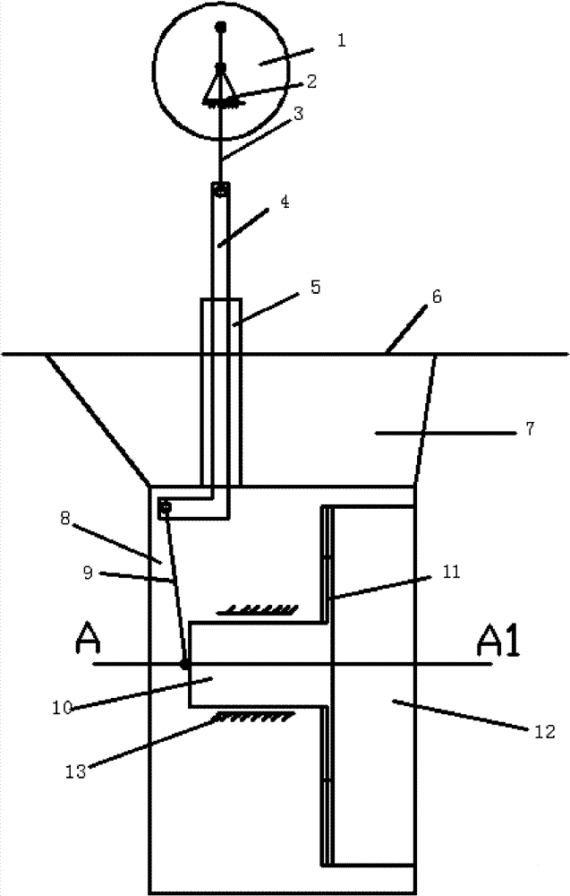
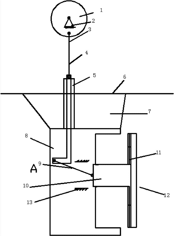
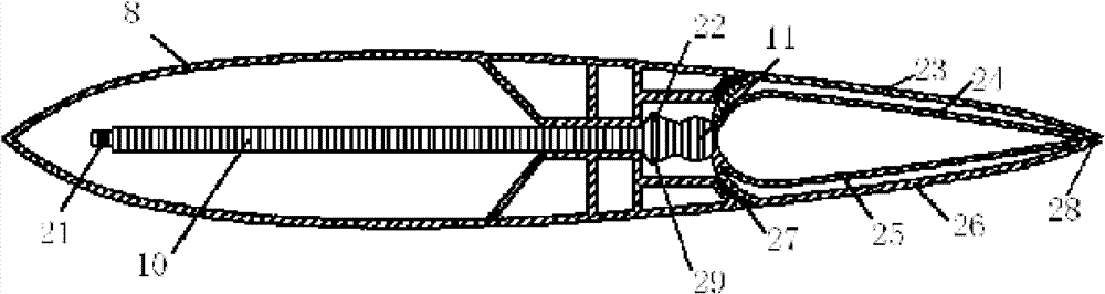
[0017] Combine below Figure 1-4 , give an example to describe the present invention in more detail:

[0018] The marine thrust rudder device of the present invention is composed of a rudder structure and a sub-rudder telescopic structure;

[0019] (1) The rudder structure consists of a rudder base 7, a main rudder 8 and a sub-rudder 12. The rudder base is fixed on the stern bottom plate 6, which is a hollow structure with a wing shape in cross section, and the front part has a cylindrical slot in which the main rudder shaft 5 is installed. The main rudder 8 is fixed on the rudder shaft 5 and can rotate together with the rudder 5 . Main rudder 8 is a hollow rectangular mechanism, and its cross section is an airfoil shape. The inside of the main rudder 8 is equipped with a frame structure 13 supporting the horizontal telescopic shaft 10. The frame structure consists of the upper front vertical frame, the upper middle vertical frame, the upper tail shell of the main rudder, t...


PUM


Abstract

The invention provides a thrust rudder comprising a rudder base, a main rudder, a sub-rudder and a sub-rudder telescopic mechanism. The sub-rudder telescopic mechanism comprises a turntable, a turntable base, a turntable connecting rod, a vertical telescopic shaft, a vertical telescopic shaft connecting rod, a horizontal telescopic shaft and a telescopic shaft connecting rod, wherein the turntable is a round flange plate which can rotate around a shaft; the turntable connecting rod is a long and thin cylinder with two ends openings for connecting the turntable and the vertical telescopic shaft, the vertical telescopic shaft is a cylinder and a lower part horizontally projects towards left near an upper and front part of the main rudder; the horizontal telescopic shaft is a flat cube, the rear part projects the horizontal telescopic shaft connecting rod; and horizontal telescopic shaft is provided with a brake block. The thrust rudder provided by the invention can meet the needs for handling and emergently thrusting a ship, improve the trust efficiency, increase the maximum ship speed and further acquire the energy-saving effect.

Description

technical field [0001] The invention relates to a ship steering device, in particular to a ship thrust rudder device. Background technique [0002] With soaring international oil prices and energy shortages, energy conservation has become a top priority for the development of the world economy. Ships are a means of transportation with high energy consumption. The research and development of ship energy-saving technologies are now attracting attention. [0003] At present, the energy-saving methods adopted by ships mainly include two aspects: reducing hull resistance and improving propulsion efficiency. Measures to improve propulsion efficiency include research on new high-efficiency and energy-saving thrusters and the development of hydrodynamic and energy-saving additional devices. The "thrust rudder" of the present invention belongs to a hydrodynamic energy-saving additional device. [0004] The rudder is generally arranged behind the propeller to meet the requirements o...

Claims


Application Information

Patent Timeline
Patent Type & Authority Patents(China)
IPC IPC(8): B63H25/38
Inventor 胡健黄胜马骋齐慧博
Owner HARBIN ENG UNIV
Why Eureka
Try Eureka