Method for operating a centrifugal separator

一种离心分离器、运行方法的技术,应用在离心分离器的运行领域,能够解决转动能量失去等问题,达到排除烦扰、排除干扰和负担的效果

Active Publication Date: 2019-12-27
HENGST WALTER
View PDF27 Cites 0 Cited by
  • Summary
  • Abstract
  • Description
  • Claims
  • Application Information

AI Technical Summary

Problems solved by technology

In addition, as the rotor coasts and decelerates, its rotational energy is lost unused

Method used


Image

  • Method for operating a centrifugal separator

Examples


Embodiment Construction

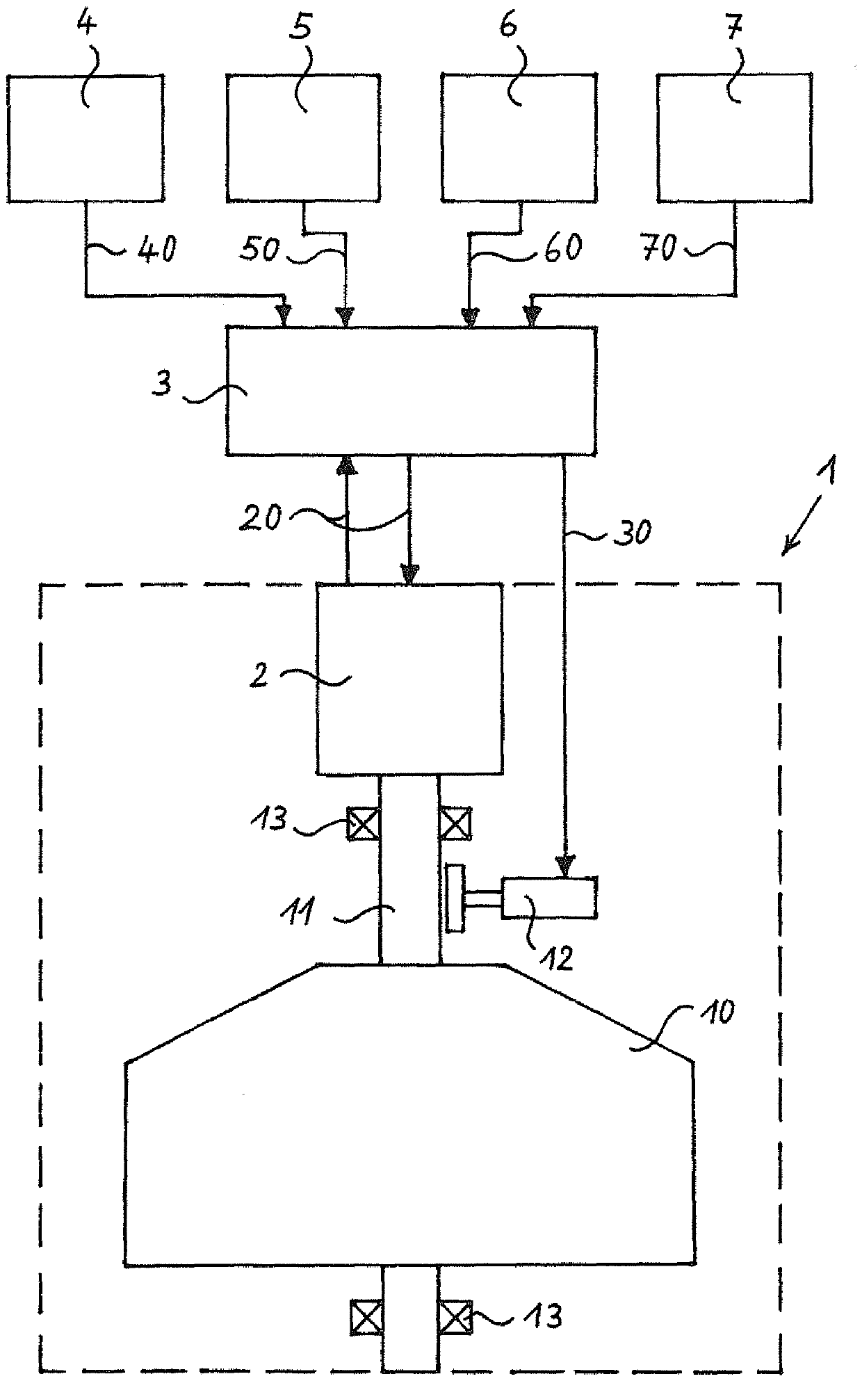
[0030] figure 1 Below it is shown schematically a centrifugal separator 1 with a rotor 10 , which is embodied as a disk separator by way of example. The rotor 10 is mounted rotatably by means of a rotor shaft 11 and two rotor bearings 13 in a separator housing, not specifically shown here. By means of a drive mechanism 2 connected to the rotor shaft 11, such as an electric motor, the rotor 10 can be rotated during the operation of the centrifugal separator 1, thereby separating microparticles of the second medium from the first medium flowing through the rotor 10 by means of centrifugal force. Drops or granules, as known per se.

[0031] Furthermore, the exemplary embodiment of the centrifugal separator 1 shown here comprises a braking mechanism 12 which, if required, applies a braking force to the rotor shaft 11 and thus also to the rotor 10 by means of friction. Alternatively, the braking mechanism 12 can also be an electrical braking mechanism, optionally with energy reco...


PUM


Abstract

The invention relates to a method for operating a centrifugal separator (1) associated with a primer mover and / or a working machine, the centrifugal separator (1) comprising at least one rotatably mounted rotor (10) that can be rotated at a variable speed by means of a drive (2) controlled by a control unit (3). The method according to the invention is characterised in that the speed of the rotor(10) is controlled according to the sound emissions of the primer mover and / or according to the sound emissions of the working machine.

Description

technical field [0001] The invention relates to a method for operating a centrifugal separator associated with a power machine and / or a work machine, wherein the centrifugal separator has at least one rotatably mounted rotor, which is configured such that, via a drive mechanism controlled by a control unit Rotate with variable speed. Background technique [0002] A method of this type described at the outset is known from documents EP1537301B1 and EP1532353B1. These documents describe methods of cleaning crankcase gases generated during operation of internal combustion engines used to drive vehicles. In this case, a centrifuge with a centrifuge rotor and an electric motor for turning the centrifuge rotor are used, the centrifuge is fastened at the vehicle for cleaning the crankcase gases, the electric motor can be connected for its operation with a power supply provided at the vehicle connect. The separation efficiency of the centrifuge is varied by changing the rotationa...

Claims


Application Information

Patent Timeline
Patent Type & Authority Applications(China)
IPC IPC(8): F01M13/04
CPCF01M13/04F01M2013/0422B04B9/10G10K11/00G10K2210/121
Inventor M.勒尔弗M.赖曼S.罗伯特
Owner HENGST WALTER
Why Eureka
Try Eureka