
Mechanism for realizing adjustable equipment rotating angle

A technology of rotation angle and equipment, which is applied in the direction of mechanical equipment, belts/chains/gears, transmission devices, etc., can solve the problems of complex use and adjustment, damage, limited angle of rotation and swing head, etc., and achieve a wide range of adjustable angles and good use effect, the effect of smooth operation

Active Publication Date: 2011-04-06
陈宗林
View PDF7 Cites 10 Cited by
  • Summary
  • Abstract
  • Description
  • Claims
  • Application Information

AI Technical Summary

Problems solved by technology

At present, there are mainly several types of rotary swing head structures for these devices: 1. The directional swing head is realized by driving the eccentric wheel and the connecting rod structure through the motor. The disadvantage is that the swing head angle is not large. When it is blocked and cannot rotate, the protective clutch mechanism will slip and fail, and its connecting rod needs to reciprocate, which is easy to cause material fatigue and damage to the connecting rod; 2. The connecting rod is used to cooperate with the chute to realize the adjustable angle, and the use and adjustment of this structure is complicated , the user is likely to make it permanently invalid due to improper adjustment; 3. The angle of the rotating swing head is adjusted through the cooperation of the worm and the gear. This structure is relatively simple, but the worm structure is blocked and the teeth of the worm gear are easily worn, causing the swing head to fail.
Moreover, the angles of rotation and swinging heads of the above several structures are relatively limited, which is not enough to meet actual needs. Although some mechanisms can adjust a small amount of rotation angle, the operation of the mechanism must be stopped before adjustment, and the operation is complicated and cumbersome.

Method used


Image

  • Mechanism for realizing adjustable equipment rotating angle
  • Mechanism for realizing adjustable equipment rotating angle
  • Mechanism for realizing adjustable equipment rotating angle

Examples


Embodiment Construction

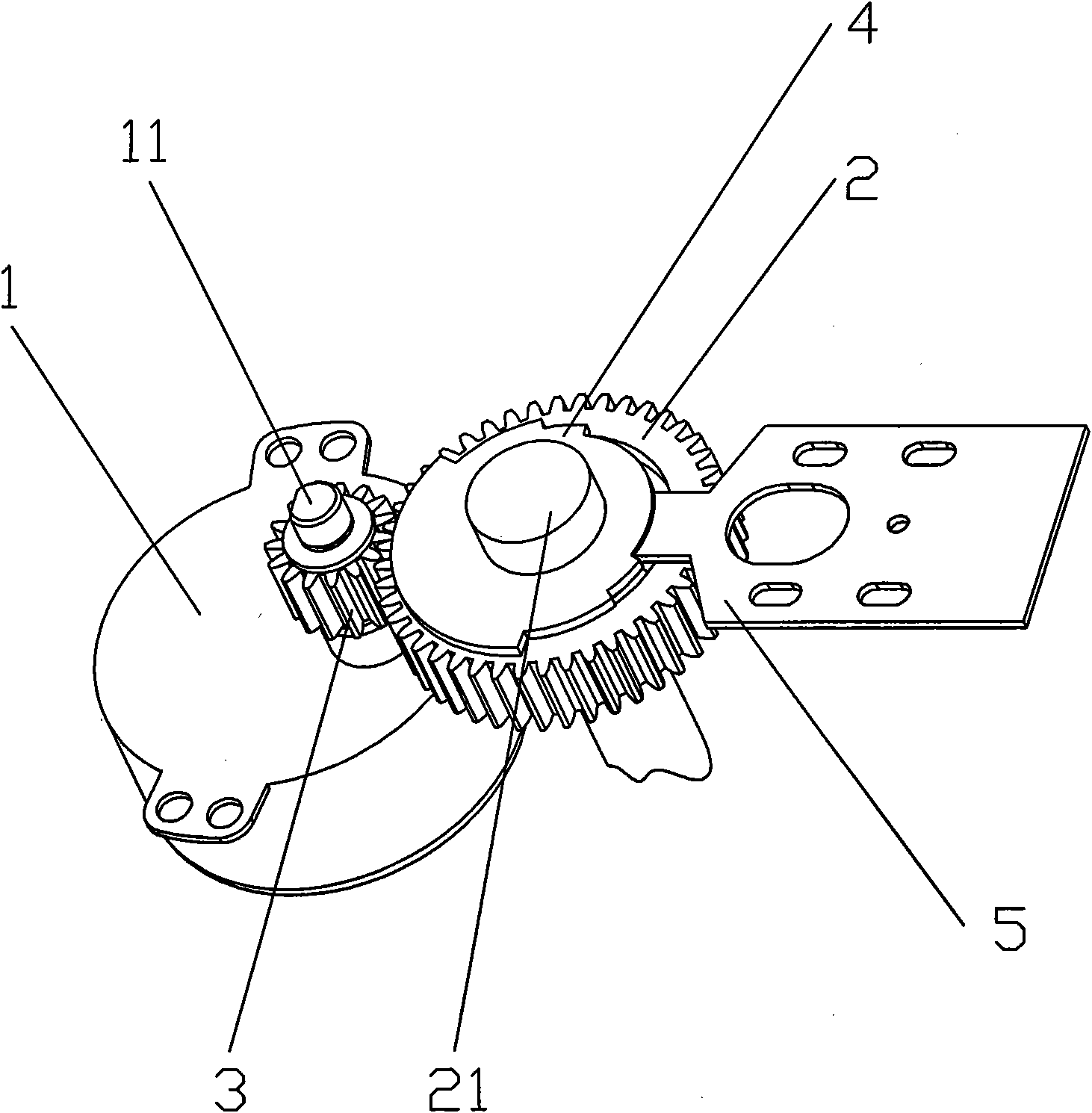
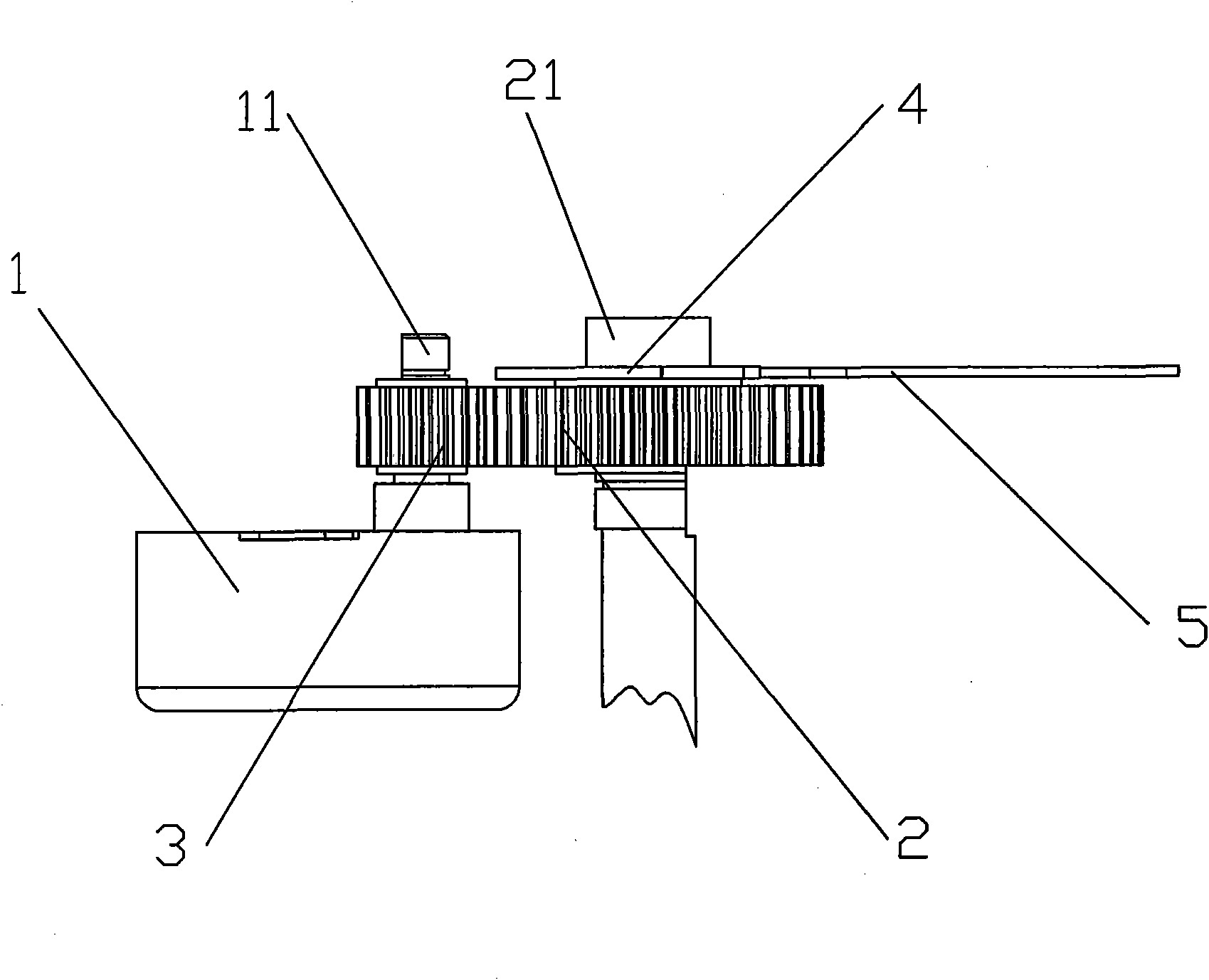
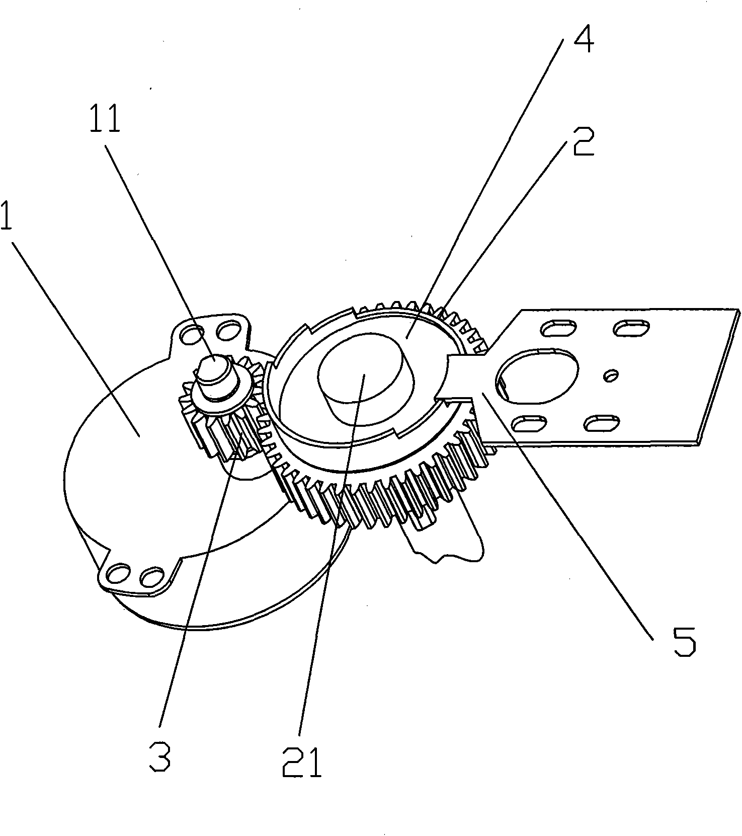
[0017] refer to figure 1 and figure 2 , a mechanism for realizing the adjustable rotation angle of the equipment in the present invention includes a synchronous motor 1, a driving gear 3 is set on the motor shaft 11 of the synchronous motor 1, and a driven gear 2 meshes with the driving gear 3, wherein the reversible synchronous The motor 1 drives the driven gear 2 to rotate through the driving gear 3 . The driven gear 2 is sleeved on the driven shaft 21, and an angle adjustment piece 4 is also sleeved on the driven shaft 21, and the outer edge of the angle adjustment piece 4 is arc-shaped. There are at least two steps of step-shaped limiting grooves on the outer edge of the angle-adjusting piece 4, and a movable baffle plate 5 is driven by a driver to extend into different limiting grooves to control the driven shaft 21 to achieve different angles of rotation and movement. The baffle 5 can be optionally installed on the shell or bracket of the fixed synchronous motor and t...


PUM


Abstract

The invention discloses a mechanism for realizing an adjustable equipment rotating angle, which comprises a synchronous motor, wherein a driving gear is sleeved on a motor main shaft of the synchronous motor; a driven gear is meshed with the driving gear and sleeved on a driven shaft; an angle adjusting piece is also sleeved on the driven shaft; an outer edge of the angle adjusting piece is in an arc shape; the outer edge of the angle adjusting piece is provided with at least two steps of step-shaped limit grooves; a movable baffle plate is driven by a drive element to extend into different limit grooves for controlling the driven shaft to realize autoroatation in different angles; and the mechanism realizes rotation by the matching of the driving gear and the driven gear and the adjustable rotating angle by the angle adjusting piece and the movable baffle plate, has the advantages of simple installation, even stress of all parts in the whole working process, stable working and running, more durable structure and wider adjustable angle range, can cover 0-360 degrees, is not only suitable for an electric fan, a heater and a fan heater but also can be applied to different equipment needing adjustable rotating angle, such as shooting equipment, search light equipment, and the like.

Description

technical field [0001] The invention relates to a rotating structure, in particular to a mechanism for realizing the adjustable rotation angle of equipment. Background technique [0002] At present, common electric fans, heaters, heaters, and cameras on the market all have the function of rotating and swinging their heads back and forth. At present, there are mainly several types of rotary swing head structures for these devices: 1. The directional swing head is realized by driving the eccentric wheel and the connecting rod structure through the motor. The disadvantage is that the swing head angle is not large. When it is blocked and cannot rotate, the protective clutch mechanism will slip and fail, and its connecting rod needs to reciprocate, which is easy to cause material fatigue and damage to the connecting rod; 2. The connecting rod is used to cooperate with the chute to realize the adjustable angle, and the use and adjustment of this structure is complicated , the use...

Claims


Application Information

Patent Timeline
Patent Type & Authority Applications(China)
IPC IPC(8): F16H49/00
Inventor 陈宗林
Owner 陈宗林
Learn More