Pluggable sliding contact line system

A sliding contact wire, plug-in technology, applied in the direction of connection, clamping/spring connection, current collector, etc., can solve the problems of troublesome installation, low impedance of copper conductor, not tight and smooth meshing, etc., saving installation time, Low impedance, the effect of increasing the current carrying capacity

Inactive Publication Date: 2012-07-25
无锡市安能滑触电器有限公司
View PDF0 Cites 0 Cited by
  • Summary
  • Abstract
  • Description
  • Claims
  • Application Information

AI Technical Summary

Problems solved by technology

[0004] The purpose of the present invention is to provide a plug-in trolley line system to overcome the need for standard parts such as screws to fasten the traditional trolley line joints during installation. The connection box and the joint are separated, which is particularly troublesome in the installation process. The lack of tightness and flatness of the meshing can avoid the diseconomy brought by the skin effect to the greatest extent, so that the copper conductor of the same cross-section has a lower impedance, and at the same time increases the current carrying capacity of the trolley line, making the ultra-large Electric current transmission device, becoming more economical and energy-saving

Method used


Image

  • Pluggable sliding contact line system
  • Pluggable sliding contact line system
  • Pluggable sliding contact line system

Examples


Embodiment Construction

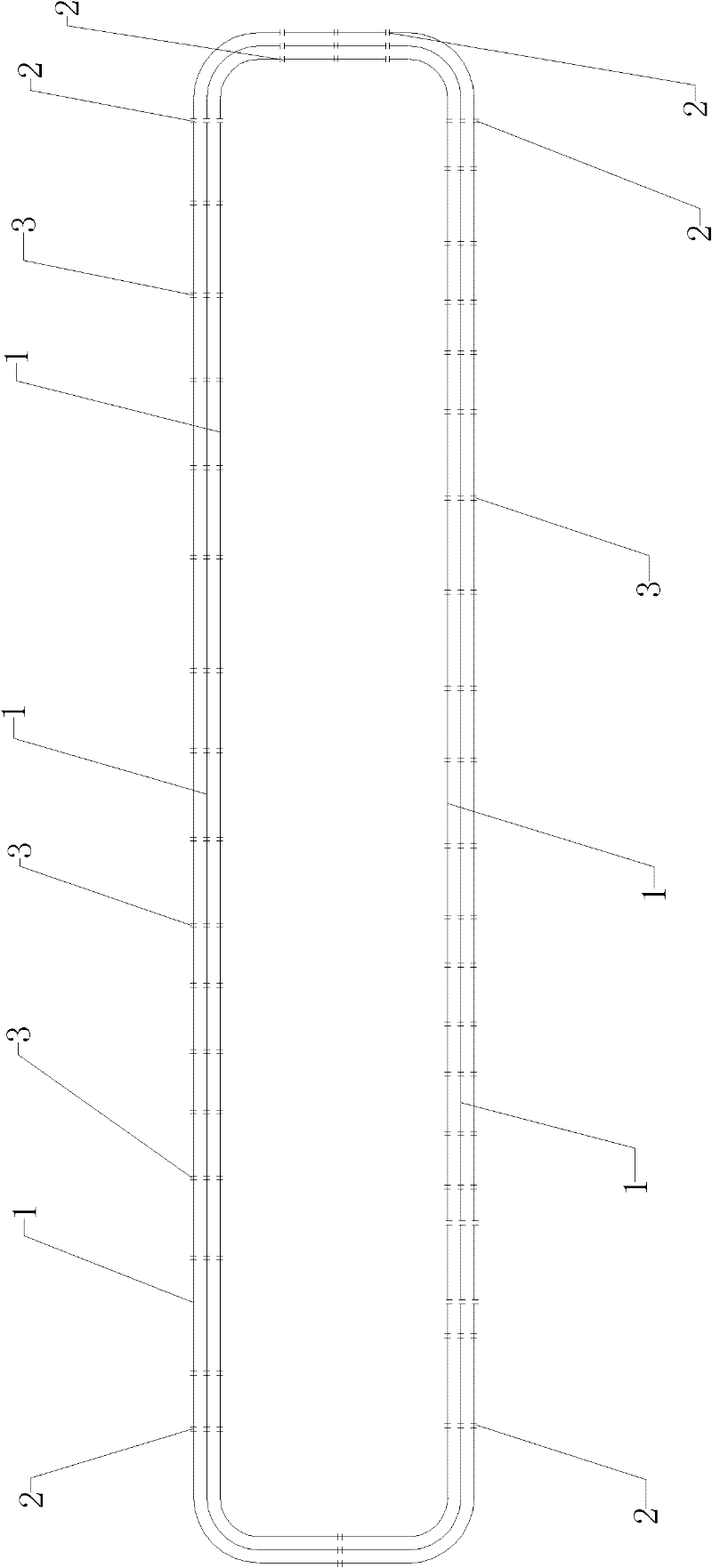
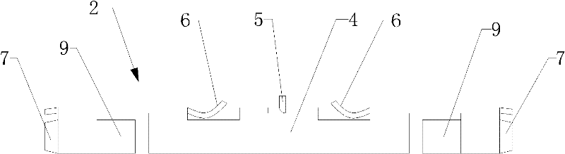
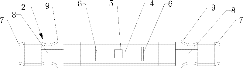
[0018] Such as Figure 1-7 As shown, a plug-in trolley line system according to the embodiment of the present invention includes several trolley lines 1 connected in sequence to form a track, wherein the segment trolley line 1 located in a straight line and its adjacent trolley line 1 are connected by an external snap-in joint 3, and the trolley line 1 at the turning and its adjacent trolley line 1 are connected by a built-in joint 2; the built-in joint 2 includes a U-shaped joint body 4, U The middle part of the top surface of the U-shaped joint main body 4 is provided with a center limit card 5, and both sides of the center limit card 5 are respectively provided with an adjustment and fixing card 6, and the two ends of the U-shaped joint main body 4 are provided with a starting card 7, and the U-shaped The top surface of the joint main body 4 and the two sides close to the entry card 7 are respectively provided with an adjustment groove 8 and a limit fixing card 9, and the l...


PUM


Abstract

The invention relates to a pluggable sliding contact line system which comprises a plurality of sliding contact lines sequentially connected into a runway shape. The sliding contact lines positioned in straight line segments are connected with adjacent sliding contact lines through outer clamping type joints, and sliding contact lines positioned in turnings are connected with the adjacent slidingcontact lines through built-in joints. The built-in joints comprise U-shaped joint bodies, the middle parts of the top face of the U-shaped joint bodies are provided with central limit cards, two adjustment fixing cards are respectively arranged at both sides of the central limit cards, starting-in cards are arranged at both ends of the U-shaped joint bodies, adjusting troughs and limit fixing cards are respectively arranged on the top face and two side faces near the starting-in cards of the U-shaped joint bodies, the outer clamping type joints comprise two connecting jackets and copper joints respectively fixed at the middle parts of the inner walls of the two connecting jackets, and the two connecting jackets are connected through flexible connecting devices. The pluggable sliding contact line system is directly plugged without being fastened by standard components, such as screws when being installed, and the installation time is saved by one third at least.

Description

technical field [0001] The invention relates to a plug-in trolley line system. Background technique [0002] At present, safety trolley lines (tubular, closed), row-type trolley lines, rigid body trolley lines, unipolar trolley lines, etc. are widely used, which have greatly improved in protection level and insulation, and are safe and reliable. But now almost all unipolar sliding contact lines in China adopt or learn from the early German WAMPFLER technology. The connection box of the joint part is separated from the joint, and is fastened by standard parts such as screws. This method is relatively simple in production process. However, it is more troublesome to install, and it is easy to cause the meshing to be insufficiently tight and smooth. [0003] Especially for large current production line trolley lines (above 100A), if the joints are not meshed tightly enough, it is easy to induce safety hazards (such as sparking at the joints, pulling the joints apart, etc.). Th...

Claims


Application Information

Patent Timeline
Patent Type & Authority Patents(China)
IPC IPC(8): H01R4/28H01R41/00
Inventor 陆春景
Owner 无锡市安能滑触电器有限公司
Why Eureka
Try Eureka