Cloud platform camera, cloud platform monitoring system and method for carrying out direction orientation

A technology of PTZ camera and PTZ, which is applied in the parts of TV system, CCTV system, image communication, etc.

Inactive Publication Date: 2011-04-06
VIMICRO CORP +1
View PDF9 Cites 31 Cited by
  • Summary
  • Abstract
  • Description
  • Claims
  • Application Information

AI Technical Summary

Problems solved by technology

[0006] The technical problem to be solved by the present invention is to provide a pan-tilt camera, a pan-tilt monitoring system and a method for locating the direction of the pan-tilt camera, so as to solve the problem that the control of the existing pan-tilt camera needs the operator to check the rotation result through the monitor to confirm The problem of the rotation direction of the gimbal

Method used


Image

  • Cloud platform camera, cloud platform monitoring system and method for carrying out direction orientation
  • Cloud platform camera, cloud platform monitoring system and method for carrying out direction orientation
  • Cloud platform camera, cloud platform monitoring system and method for carrying out direction orientation

Examples


Embodiment Construction

[0038] In order to make the above objects, features and advantages of the present invention more comprehensible, the present invention will be further described in detail below in conjunction with the accompanying drawings and specific embodiments.

[0039] In order to quickly locate the specific position of the monitored object, the present invention improves the existing pan-tilt camera so that it has the function of collecting azimuth data and superimposing it with the video image, and the monitoring user can know the specific location of the monitored object through the display of the monitor. position.

[0040] The following will be described in detail through examples.

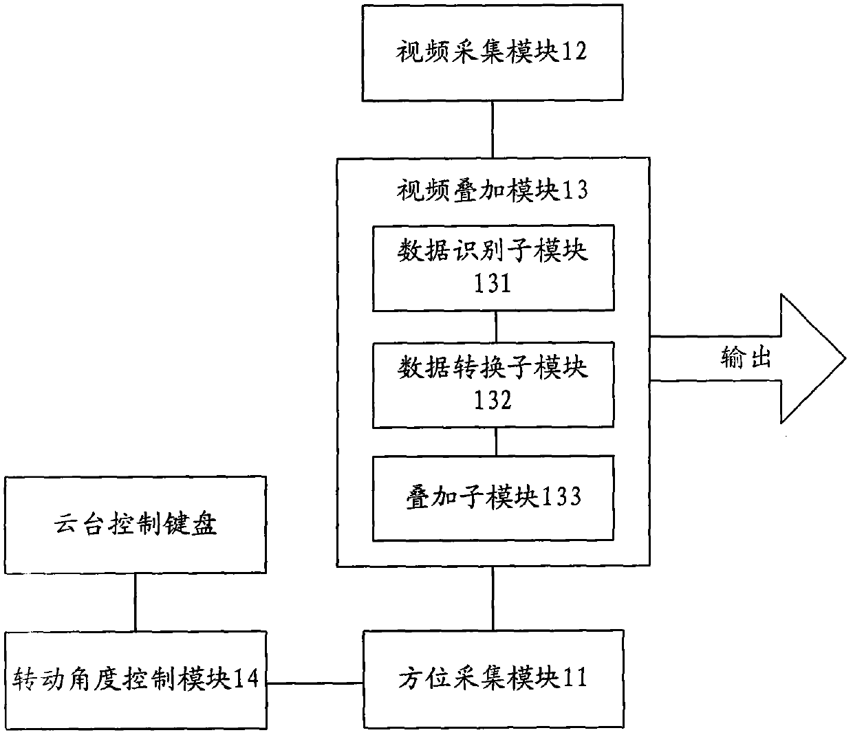
[0041] refer tofigure 1 , is a structural diagram of a pan-tilt camera according to an embodiment of the present invention.

[0042] Described PTZ camera comprises azimuth acquisition module 11, video acquisition module 12 and video overlay module 13, and wherein azimuth acquisition module 11 is used fo...


PUM


Abstract

The invention discloses a cloud platform camera, a cloud platform monitoring system and a method for carrying out direction orientation by the cloud platform camera, which can solve the problem that the traditional cloud platform camera is controlled by operating personnel watching the rotating result via a monitor to confirm the rotating direction of the cloud platform. The cloud platform camera comprises: a direction collecting module, a video collecting module and a video superposing module, wherein the direction collection module is used for collecting spot original direction data in real time; the video collecting module is used for collecting spot original video data in real time; and the video superposing module is used for superposing and inputting the original direction data and the original video data. Therefore, both video images and the corresponding superposed three-dimensional direction data can be displayed on the monitor. Reference parameters can be provided by the cloud platform camera of the invention, therefore a monitoring user can rapidly orientate the specific position of a questionable object; even being unfamiliar with the monitoring scene, the operating personnel beside the monitor can recognize whether the present area displayed on the monitor needs attention or not according to the three-dimensional direction data displayed in real time.

Description

technical field [0001] The invention relates to video monitoring technology, in particular to a pan-tilt camera, a pan-tilt monitoring system and a method for locating the direction of the pan-tilt camera. Background technique [0002] The camera is an indispensable component of the monitoring and security system. It is responsible for collecting front-end images and transmitting them to the monitoring room through coaxial cables or converting them into digital data through the network, and displaying them on the monitor to realize real-time space conversion on site. [0003] In a general small-scale monitoring environment, ordinary cameras are usually used, but in large-scale monitoring environments such as safe cities, ordinary cameras cannot collect a wider range of the scene due to the limitation of the viewing angle range, forming a monitoring blind spot, so we choose to use the cloud camera. The PTZ camera can collect all-round on-site images through the rotatable len...

Claims


Application Information

Patent Timeline
Patent Type & Authority Applications(China)
IPC IPC(8): H04N7/18H04N5/262G05D3/12
Inventor 柳文凭
Owner VIMICRO CORP
Why Eureka
Try Eureka