Fabric draw-off device

A technology of fabrics and circular knitting machines, applied in the direction of knitting, weft knitting, textiles and papermaking, which can solve time-consuming and troublesome problems

Inactive Publication Date: 2011-04-06
MEMMINGER IRO GMBH
View PDF1 Cites 4 Cited by
  • Summary
  • Abstract
  • Description
  • Claims
  • Application Information

AI Technical Summary

Problems solved by technology

If the operator needs to modify the gear ratio, he has to cha

Method used


Image

  • Fabric draw-off device
  • Fabric draw-off device
  • Fabric draw-off device

Examples


Embodiment Construction

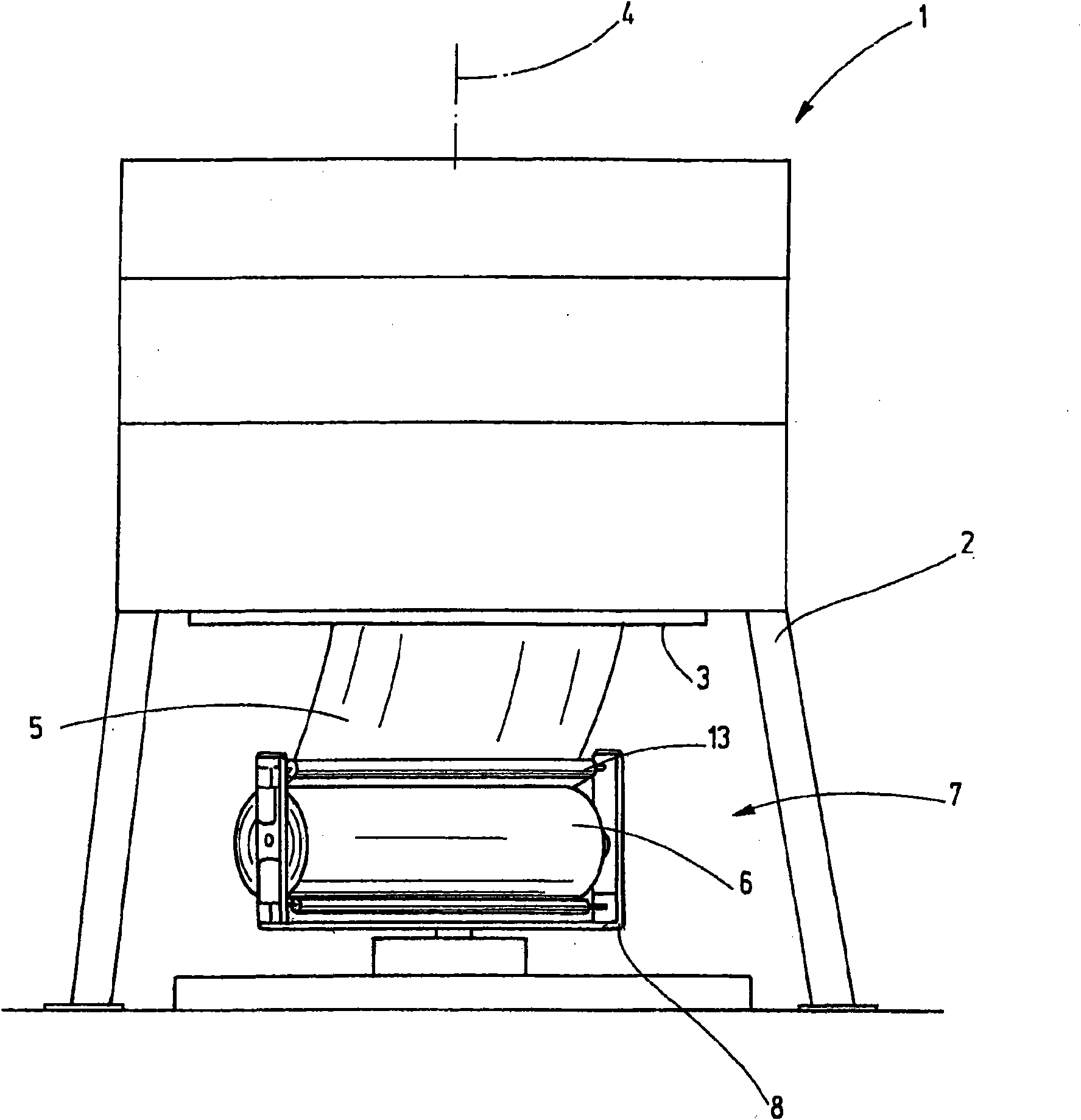
[0035] With reference to the accompanying drawings, especially figure 1 , where a circular knitting machine 1 is shown highly schematically. The rotary knitting machine 1 comprises a stationary frame 2 supporting a hollow knitting cylinder 3 about a vertical axis of rotation 4 . A main drive (not shown) is provided for rotating the knitting cylinder 3 in a defined direction.

[0036] In operation, the knitwear 5 leaves the cylinder 3 and travels downwards. The knitwear 5 is usually tubular. It has to be coiled to form bales 6 or rolls. The knitwear 5 can be slit longitudinally and spread out into individual pieces to be rolled up. Alternatively, the fabric tube may remain uncut. In the latter case, the knitwear forms a double layer in each winding of the bale 6 .

[0037] The extraction device 7 is located below the knitting cylinder 3 for extracting the knitwear 5 downwards and for winding the knitwear 5 . The extraction device 7 pulls down and holds the fabric 5, whic...


PUM


Abstract

An electrically driven fabric draw-off device (7) is disclosed which uses at least one electric motor (16) for driving at least one draw-off roller (13, 14, 15). The electric power is supplied via a rotary electrical interface which electrically connects the motor (16) on rotating frame (8) to the stationary electric supply (34). The rotational movement of frame (8) is caused by another electric motor (26) which is driven in response to a signal indicating the rotational movement of the cylinder (3) of knitting machine (1).

Description

technical field [0001] The invention relates to a fabric extraction device for taking up fabric released from a circular knitting machine and applying a defined longitudinal force to the fabric. Background technique [0002] Circular knitting machines (or knitting machines) typically release a tubular knit. In particular, large knitting machines are known for producing endless tubular knitwear which is to be wound up by large rollers. As is known, due to the rotational movement of the knitting cylinders of circular knitting machines, the knitwear rotates about a vertical axis. Thus, it is necessary to rotate also the horizontal axis of the knitwear being taken up around said vertical axis at a speed equal to the rotation speed of said knitting cylinder. Thus, the known withdrawal device comprises a mechanical transmission connecting the drive of the knitting cylinder to the rotating frame of the take-up roller. When using this concept, the extraction device increases the ...

Claims


Application Information

Patent Timeline
IPC IPC(8): D04B15/88
CPCD04B15/88
Inventor F·奥内达
Owner MEMMINGER IRO GMBH
Why Eureka
Try Eureka